Last Updated: 04/24/2025 1:46 AM
The following table lists all the components that make up the document.
Removal and replacement of AM-270 remote alarm panel (RAP).
Hour
Coordinate site access with operators
7264 - 1401 - Establish Initial Conditions; Remark:
1401 - Establish Initial Conditions
Establish Initial Conditions
7622 - 7592 - Inform system operators; Remark:11335
7592 - Inform system operators
Inform system operators
11335 - Upon arrival, brief system operators on expected work, duration, anticipated ...
Upon arrival, brief system operators on expected work, duration, anticipated alarms, and fault indications before starting work.
10334 - 7676 - Brief system operators on expected work, duration, anticipated alarms, and fa...; Remark:
7676 - Brief system operators on expected work, duration, anticipated alarms, and fa...
Brief system operators on expected work, duration, anticipated alarms, and fault indications before starting work
7268 - 7231 - Close lane; Remark:7233
9053 - Warning : Traffic should temporarily be rerouted or halted during conduction of this pr...
Traffic should temporarily be rerouted or halted during conduction of this procedure to ensure maintenance provider safety and to prevent unscreened vehicles from passing.
7231 - Close lane
Close lane
7233 - Use orange safety (traffic control) cones to setup barriers. Practice establi...
Use orange safety (traffic control) cones to setup barriers. Practice established safety protocols.
9859 - 9786 - Shutdown AM-270 Remove Alarm Panel; Remark:
9786 - Shutdown AM-270 Remove Alarm Panel
Shutdown AM-270 Remove Alarm Panel
9860 - 9787 - Lift cover fully open; Remark:9788
9787 - Lift cover fully open
Lift cover fully open
9788 - Cover screws will not fully come out. Utilizing a PH2 screwdriver, loosen unt...
Cover screws will not fully come out. Utilizing a PH2 screwdriver, loosen until cover can be lifted.

9865 - 9789 - Power off AM-270; Remark:9790
9789 - Power off AM-270
Power off AM-270
9790 - Flip toggle switch to off position (towards you).
Flip toggle switch to off position (towards you).

9866 - 9791 - Deenergize AM-270; Remark:9792
9791 - Deenergize AM-270
Deenergize AM-270
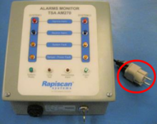
9792 - Unplug AC power cable from wall outlet.
Unplug AC power cable from wall outlet.
9867 - 9793 - Disconnect positive battery wire; Remark:9794
7792 - Note : It is good engineering practice to ensure all cables and connectors are label...
It is good engineering practice to ensure all cables and connectors are labeled before disconnecting them.
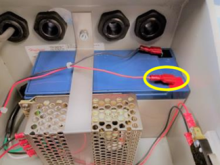
9793 - Disconnect positive battery wire
Disconnect positive battery wire
9868 - 9795 - Disconnect negative battery wire; Remark:9796
7792 - Note : It is good engineering practice to ensure all cables and connectors are label...
It is good engineering practice to ensure all cables and connectors are labeled before disconnecting them.
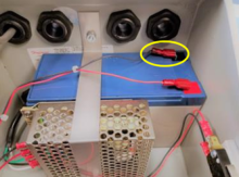
9795 - Disconnect negative battery wire
Disconnect negative battery wire
9875 - 9797 - Uninstall Faulty AM-270 Remote Alarm Panel; Remark:
9797 - Uninstall Faulty AM-270 Remote Alarm Panel
Uninstall Faulty AM-270 Remote Alarm Panel
9876 - 9798 - Remove signal wires; Remark:9799
7792 - Note : It is good engineering practice to ensure all cables and connectors are label...
It is good engineering practice to ensure all cables and connectors are labeled before disconnecting them.
9798 - Remove signal wires
Remove signal wires
9799 - Utilizing an insertion tool (Part #: 2855B), remove signal wires.
Utilizing an insertion tool (Part #: 2855B), remove signal wires.

9877 - 9800 - Loosen cable nuts; Remark:9801
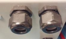
9800 - Loosen cable nuts
Loosen cable nuts
9801 - Utilizing an adjustable wrench, loosen nuts on back of AM-270.
Utilizing an adjustable wrench, loosen nuts on back of AM-270.
9878 - 9802 - Remove signal cables from back of AM-270; Remark:
7792 - Note : It is good engineering practice to ensure all cables and connectors are label...
It is good engineering practice to ensure all cables and connectors are labeled before disconnecting them.
9802 - Remove signal cables from back of AM-270
Remove signal cables from back of AM-270
9879 - 9803 - Close the cover; Remark:9804
9803 - Close the cover
Close the cover
9804 - Utilizing a PH2 screwdriver, tighten AM-270 cover.
Utilizing a PH2 screwdriver, tighten AM-270 cover.
3397 - 3395 - Label faulty component; Remark:3396
3395 - Label faulty component
Label faulty component
3396 - Use tag or tape. Include date of removal, description of failure symptoms, co...
Use tag or tape. Include date of removal, description of failure symptoms, country, site, and lane number. Dispose per Nuclear Smuggling Detection and Deterrence (NSDD) guidance or contractual requirements.
9880 - 9805 - Install New AM-270 Remote Alarm Panel; Remark:
9805 - Install New AM-270 Remote Alarm Panel
Install New AM-270 Remote Alarm Panel
9881 - 9806 - Set new AM-270 where old unit was; Remark:
9806 - Set new AM-270 where old unit was
Set new AM-270 where old unit was
9882 - 9807 - Lift cover fully open; Remark:9788
9807 - Lift cover fully open
Lift cover fully open
9788 - Cover screws will not fully come out. Utilizing a PH2 screwdriver, loosen unt...
Cover screws will not fully come out. Utilizing a PH2 screwdriver, loosen until cover can be lifted.
9883 - 9808 - Insert signal wire cables to the same depth as in old unit; Remark:
9808 - Insert signal wire cables to the same depth as in old unit
Insert signal wire cables to the same depth as in old unit
9890 - 9809 - Tighten cable nuts; Remark:9810
9809 - Tighten cable nuts
Tighten cable nuts
9810 - Using an adjustable wrench, tighten nuts on back of AM-270.
Using an adjustable wrench, tighten nuts on back of AM-270.
9891 - 9811 - Install signal wires; Remark:9812
7808 - Caution : Proper connection of wiring harnesses is critical.
Proper connection of wiring harnesses is critical.
9811 - Install signal wires
Install signal wires
9812 - Utilizing an insertion tool (Part #: 2855B), install signal wires.
Utilizing an insertion tool (Part #: 2855B), install signal wires.
9893 - 9813 - Plug AC power cable into wall outler; Remark:9814
9813 - Plug AC power cable into wall outler
Plug AC power cable into wall outler
9814 - The LED light on the power supply should be on.
The LED light on the power supply should be on.
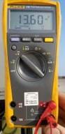
9894 - 9815 - Check Power Supply Voltage; Remark:
9815 - Check Power Supply Voltage
Check Power Supply Voltage
9895 - 9816 - Set digital multimeter to DC volts; Remark:9817
9816 - Set digital multimeter to DC volts
Set digital multimeter to DC volts

9896 - 9818 - Connect digital multimeter negative test lead to ground; Remark:
9818 - Connect digital multimeter negative test lead to ground
Connect digital multimeter negative test lead to ground
9897 - 9819 - Connect digital multimeter positive lead to red wire terminal on power supply...; Remark:9820
9819 - Connect digital multimeter positive lead to red wire terminal on power supply...
Connect digital multimeter positive lead to red wire terminal on power supply
9820 - The digital multimeter should read 13.6 VDC. If the digital multimeter doesn'...
The digital multimeter should read 13.6 VDC. If the digital multimeter doesn't read 13.6 VDC, adjust the power supply voltage.
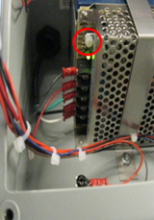
9906 - 9824 - Adjust Power Supply Voltage (if applicable); Remark:
9824 - Adjust Power Supply Voltage (if applicable)
Adjust Power Supply Voltage (if applicable)
9907 - 9822 - Turn trim potentiometer until voltage reaches 13.6 VDC on digital multimeter....; Remark:9823
9821 - Warning : 90-240 VAC is present near the point where power supply voltage adjustments a...
90-240 VAC is present near the point where power supply voltage adjustments are made. Take care not to allow tools to come into contact with 90-240 VAC connections or terminal strip.
9822 - Turn trim potentiometer until voltage reaches 13.6 VDC on digital multimeter....
Turn trim potentiometer until voltage reaches 13.6 VDC on digital multimeter.
9823 - Turning the trim potentiometer clockwise will increase the voltage.
Turning the trim potentiometer clockwise will increase the voltage.
Turning the trim potentiometer counterclockwise will decrease the voltage.
9908 - 9825 - Power On AM-270; Remark:
9825 - Power On AM-270
Power On AM-270
9909 - 9826 - Connect negative battery wire; Remark:9796
7811 - Caution : Proper connection of cables is critical.
Proper connection of cables is critical.
9826 - Connect negative battery wire
Connect negative battery wire
9915 - 9828 - Connect positive battery wire; Remark:9794
7811 - Caution : Proper connection of cables is critical.
Proper connection of cables is critical.
9828 - Connect positive battery wire
Connect positive battery wire
9916 - 9825 - Power On AM-270; Remark:9829
9825 - Power On AM-270
Power On AM-270
9829 - Flip toggle switch to on position (away from you).
Flip toggle switch to on position (away from you).
9917 - 9830 - Verify AM-270 lights; Remark:9831
9830 - Verify AM-270 lights
Verify AM-270 lights
9831 - Verify Systems Ready and Power On lights ar...
Verify Systems Ready and Power On lights are lit.
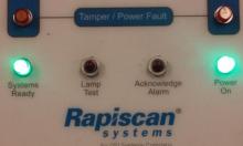
7279 - 7249 - Return equipment to normal operating condition; Remark:
7249 - Return equipment to normal operating condition
Return equipment to normal operating condition
9918 - 9832 - Turn key on bottom of AM-270 vertical; Remark:
9832 - Turn key on bottom of AM-270 vertical
Turn key on bottom of AM-270 vertical
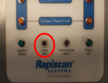
9919 - 9833 - Push Lamp Test switch; Remark:9834
9833 - Push Lamp Test switch
Push Lamp Test switch
9834 - Verify all lights flash.
Verify all lights flash.
9920 - 9835 - Turn key on bottom of AM-270 horizontal; Remark:
9835 - Turn key on bottom of AM-270 horizontal
Turn key on bottom of AM-270 horizontal
9924 - 9833 - Push Lamp Test switch; Remark:9836
9833 - Push Lamp Test switch
Push Lamp Test switch
9836 - All lights should flash and siren should sound a steady noise.
All lights should flash and siren should sound a steady noise.
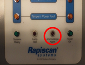
9925 - 9837 - Push Acknowledge Alarm button to silence siren; Remark:9838
9837 - Push Acknowledge Alarm button to silence siren
Push Acknowledge Alarm button to silence siren
9927 - 9830 - Verify AM-270 lights; Remark:9831
9830 - Verify AM-270 lights
Verify AM-270 lights
9831 - Verify Systems Ready and Power On lights ar...
Verify Systems Ready and Power On lights are lit.
9926 - 9839 - Tighten AM-270 cover screws; Remark:9849
9839 - Tighten AM-270 cover screws
Tighten AM-270 cover screws
9929 - 319 - Perform operational test; Remark:9347
319 - Perform operational test
Perform operational test
9347 - DET-RPM-RAP-RM03 RPM Operational Testing.
DET-RPM-RAP-RM03 RPM Operational Testing.
322 - 321 - Document maintenance actions; Remark:
321 - Document maintenance actions
Document maintenance actions
2869 - 2585 - Document maintenance performed; Remark:2866
2585 - Document maintenance performed
Document maintenance performed
2866 - Record observations, times, and results for the maintenance report.
Record observations, times, and results for the maintenance report.
4706 - 4705 - Submit report; Remark:4864
4705 - Submit report
Submit report
4864 - As specified by management or contractual obligations.
As specified by management or contractual obligations.