Last Updated: 04/24/2025 1:45 AM
The following table lists all the components that make up the document.
Replace a faulty +15 Vdc [volts direct current] power supply
Verify 13.6 Vdc is present at the DC output
Prior to arrival, notify operators concerning expected work, duration, and anticipated alarms and fault indications.
Updated instructions and departmental coordination
1402 - 7927 - Establish Initial Conditions; Remark:
7927 - Establish Initial Conditions
Establish Initial Conditions
7268 - 7231 - Close lane; Remark:7233
9053 - Warning : Traffic should temporarily be rerouted or halted during conduction of this pr...
Traffic should temporarily be rerouted or halted during conduction of this procedure to ensure maintenance provider safety and to prevent unscreened vehicles from passing.
7231 - Close lane
Close lane
7233 - Use orange safety (traffic control) cones to setup barriers. Practice establi...
Use orange safety (traffic control) cones to setup barriers. Practice established safety protocols.
7269 - 7232 - Open RPM door; Remark:7234
7232 - Open RPM door
Open RPM door
7234 - Open all doors needed to access components.
Open all doors needed to access components.
7270 - 7235 - Power off RPM; Remark:7236
7235 - Power off RPM
Power off RPM
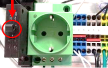
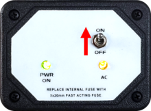
7236 - Move LD-260 switch to OFF position. The PWR ON
Move LD-260 switch to OFF position. The PWR ON LED will turn off.

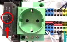
9740 - 9739 - Turn main breaker to “off” (down) position; Remark:9738
9783 - Note : If there is voltage present at the power supply after switching the main brea...
If there is voltage present at the power supply after switching the main breaker off, then locate a main power breaker (possibly located in the utility panel) that feeds AC to the RPM and shut the power off there.
9739 - Turn main breaker to “off” (down) position
Turn main breaker to “off” (down) position
9738 -
9737 - 9736 - Uninstall Faulty Power Supply; Remark:
9736 - Uninstall Faulty Power Supply
Uninstall Faulty Power Supply
9765 - 9763 - Verify there is no voltage present at power supply; Remark:9762
7792 - Note : It is good engineering practice to ensure all cables and connectors are label...
It is good engineering practice to ensure all cables and connectors are labeled before disconnecting them.
9764 - Warning : Lethal currents may be present. Verify breaker is open and 110-220 Vac is not...
Lethal currents may be present. Verify breaker is open and 110-220 Vac is not present at the input to the +15Vdc power supply.
9763 - Verify there is no voltage present at power supply
Verify there is no voltage present at power supply
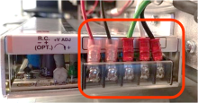
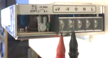
9762 - Check for AC voltage at the input on the power supply using the digital multi...
Check for AC voltage at the input on the power supply using the digital multi meter (DMM). The Red (+) DMM lead is placed at the black wire or Line. The Black (-) DMM lead is placed at the ground (Green).
9766 - 9761 - Loosen screws to disconnect wires to the power supply; Remark:9760
9761 - Loosen screws to disconnect wires to the power supply
Loosen screws to disconnect wires to the power supply
9760 - Use a medium Philips screwdriver. It is unnecessary to loosen the screws comp...
Use a medium Philips screwdriver. It is unnecessary to loosen the screws completely.
9767 - 9759 - Remove mounting plate; Remark:9758
9759 - Remove mounting plate
Remove mounting plate
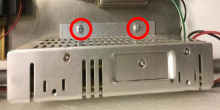
9758 - Remove two screws that attach the bracket of power supply to the mounting pla...
Remove two screws that attach the bracket of power supply to the mounting plate using a medium Philips screwdriver.
9768 - 9757 - Remove two screws from bracket attached to power supply; Remark:9756
9757 - Remove two screws from bracket attached to power supply
Remove two screws from bracket attached to power supply
9756 -

3397 - 3395 - Label faulty component; Remark:3396
3395 - Label faulty component
Label faulty component
3396 - Use tag or tape. Include date of removal, description of failure symptoms, co...
Use tag or tape. Include date of removal, description of failure symptoms, country, site, and lane number. Dispose per Nuclear Smuggling Detection and Deterrence (NSDD) guidance or contractual requirements.
9755 - 9754 - Install New Power Supply; Remark:
9754 - Install New Power Supply
Install New Power Supply
9751 - 9750 - Attach bracket onto new power supply using screws from previous mounting setu...; Remark:9749
9750 - Attach bracket onto new power supply using screws from previous mounting setu...
Attach bracket onto new power supply using screws from previous mounting setup
9749 - If existing screws are not available, use two M4X6 FP screws...
If existing screws are not available, use two M4X6 FP screws.
9752 - 9748 - Attach power supply to mounting plate; Remark:9747
9748 - Attach power supply to mounting plate
Attach power supply to mounting plate
9747 - Use screws from previous mounting setup. If existing screws are not available...
Use screws from previous mounting setup. If existing screws are not available, use two M4X8 PP screws.
9753 - 9746 - Connect wires back to their designated positions; Remark:9745
9746 - Connect wires back to their designated positions
Connect wires back to their designated positions
9745 - Use a medium Philips screwdriver.
Use a medium Philips screwdriver.
7279 - 7249 - Return equipment to normal operating condition; Remark:
7249 - Return equipment to normal operating condition
Return equipment to normal operating condition
9776 - 9774 - Turn main breaker to “on” (up) position; Remark:9773
9775 - Caution : Do not toggle the LD-260 switch before measuring the AC voltage at the input ...
Do not toggle the LD-260 switch before measuring the AC voltage at the input on the power supply and the DC voltage at the power supply.
9774 - Turn main breaker to “on” (up) position
Turn main breaker to “on” (up) position
9777 - 9772 - Check for AC voltage at input on power supply using DMM; Remark:9771
10271 - Note : Depending on country of installation, voltage should be between 110-240 VAC.
Depending on country of installation, voltage should be between 110-240 VAC.
9772 - Check for AC voltage at input on power supply using DMM
Check for AC voltage at input on power supply using DMM
9771 - The Red (+) DMM lead is placed at the black wire or Line. The Black (-) DMM l...
The Red (+) DMM lead is placed at the black wire or Line. The Black (-) DMM lead is placed at the ground (Green).
9778 - 9770 - Verify DC voltage at power supply is 13.6 Vdc using DMM; Remark:9769
9770 - Verify DC voltage at power supply is 13.6 Vdc using DMM
Verify DC voltage at power supply is 13.6 Vdc using DMM
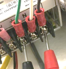
9769 - With leads located at the DC output of the power supply. Position the Red (+)...
With leads located at the DC output of the power supply. Position the Red (+) DMM lead at the red wire, and the Black (-) DMM lead at the black wire.
9782 - 9781 - Adjust Voltage as needed; Remark:9779
9781 - Adjust Voltage as needed
Adjust Voltage as needed
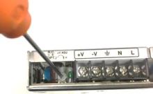
9779 - Use trim pot located next to terminals to adjust when improper voltage is mea...
Use trim pot located next to terminals to adjust when improper voltage is measured using a small Philips screwdriver.
9780 - With leads in place, either adjust up (clockwise) or down (counter-clockwise)...
With leads in place, either adjust up (clockwise) or down (counter-clockwise) by turning the trim pot until 14.6 Vdc is measured as the output.
7280 - 7250 - Power on RPM; Remark:7251
7250 - Power on RPM
Power on RPM
7251 - Move LD-260 switch to ON position. The LED PWR ON
Move LD-260 switch to ON position. The LED PWR ON will illuminate.
9735 - 319 - Perform operational test; Remark:9733
319 - Perform operational test
Perform operational test
9733 - DET-RPM-RAP-RM03.
DET-RPM-RAP-RM03.
7842 - 7820 - Inform system operators upon completion of maintenance action; Remark:
7820 - Inform system operators upon completion of maintenance action
Inform system operators upon completion of maintenance action
322 - 321 - Documentați acțiunile de întreținere; Remark:
321 - Documentați acțiunile de întreținere
Documentați acțiunile de întreținere
2869 - 2585 - Documentați acțiunile de întreținere întreprinse; Remark:2866
2585 - Documentați acțiunile de întreținere întreprinse
Documentați acțiunile de întreținere întreprinse
2866 - Notați observațiile și rezultatele pentru Raportul de întreținere corect...
Notați observațiile și rezultatele pentru Raportul de întreținere corectivă.
4706 - 4705 - Submit report; Remark:4864
4705 - Submit report
Submit report
4864 - As specified by management or contractual obligations.
As specified by management or contractual obligations.