Last Updated: 04/24/2025 1:44 AM
The following table lists all the components that make up the document.
Install the ThetaController to replace both the GE VersaMax Nano Controller, Model# IC200NDR010 (Rapiscan Part #6661N) and the RS232 to RS485 Converter (Rapiscan Part #2725A) on the radiation portal monitor (RPM).
Verify Speed message
Prior to arrival, notify operators concerning expected work, duration, and anticipated alarms and fault indications.
Updated LD-260 Power on instructions and images to re-usable standard content.
1402 - 7927 - Başlangıç Koşullarını belirleyin; Remark:
7927 - Başlangıç Koşullarını belirleyin
Başlangıç Koşullarını belirleyin
7268 - 7231 - Close lane; Remark:7233
9053 - Warning : Traffic should temporarily be rerouted or halted during conduction of this pr...
Traffic should temporarily be rerouted or halted during conduction of this procedure to ensure maintenance provider safety and to prevent unscreened vehicles from passing.
7231 - Close lane
Close lane
7233 - Use orange safety (traffic control) cones to setup barriers. Practice establi...
Use orange safety (traffic control) cones to setup barriers. Practice established safety protocols.
7269 - 7232 - Open RPM door; Remark:7234
7232 - Open RPM door
Open RPM door
7234 - Open all doors needed to access components.
Open all doors needed to access components.
7454 - 7290 - Disable tamper switches; Remark:7416
7290 - Disable tamper switches
Disable tamper switches
7416 - Use a magnet to disable tamper switches for all open doors. Use adhesive tape...
Use a magnet to disable tamper switches for all open doors. Use adhesive tape to disable older mechanical switches.
8281 - 8280 - Disable both infrared occupancy sensors; Remark:8279
7351 - Note : It is good practice to verify all cables and connectors are labeled prior to ...
It is good practice to verify all cables and connectors are labeled prior to disconnection.
8280 - Disable both infrared occupancy sensors
Disable both infrared occupancy sensors
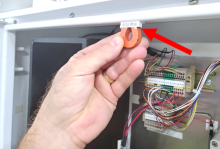
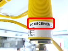
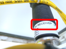
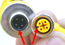
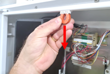
8279 - Verify sensors mounted in control pillar door are receivers
Verify sensors mounted in control pillar door are receivers
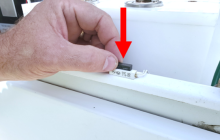
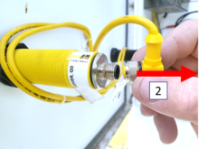
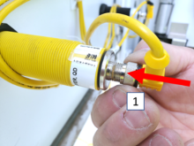
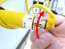
8287 - To disconnect sensor cable, turn collar counterclockwise and pull away from s...
To disconnect sensor cable, turn collar counterclockwise and pull away from sensor.

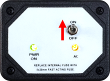
7270 - 7235 - Power off RPM; Remark:7236
7235 - Power off RPM
Power off RPM
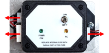
7236 - Move LD-260 switch to OFF position. The PWR ON
Move LD-260 switch to OFF position. The PWR ON LED will turn off.

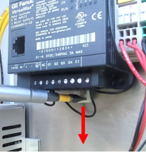
8344 - 8343 - Locate RS232 to RS485 Converter; Remark:8341
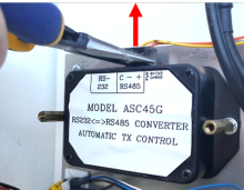
8343 - Locate RS232 to RS485 Converter
Locate RS232 to RS485 Converter
8341 - For vehicle monitors (VM-250), the converter is located behind the LD-260...
For vehicle monitors (VM-250), the converter is located behind the LD-260

8342 - For train monitors (TM-850), the converter is usually located in the electron...
For train monitors (TM-850), the converter is usually located in the electronics cabinet on the control pillar

8340 - 8339 - Uninstall LD-260 (VM-250 only); Remark:
8339 - Uninstall LD-260 (VM-250 only)
Uninstall LD-260 (VM-250 only)
7272 - 7238 - Disconnect three (3) connectors; Remark:7239
5291 - Note : It is good practice to verify all cables and connectors are labeled prior to ...
It is good practice to verify all cables and connectors are labeled prior to disconnection.
7238 - Disconnect three (3) connectors
Disconnect three (3) connectors
7239 - Needle nose pliers can be used to remove connectors.
8347 - 8346 - Remove two (2) mounting screws; Remark:8345
8346 - Remove two (2) mounting screws
Remove two (2) mounting screws
8345 - Use medium Phillips (PH2) screwdriver. Retain screws.
Use medium Phillips (PH2) screwdriver. Retain screws.
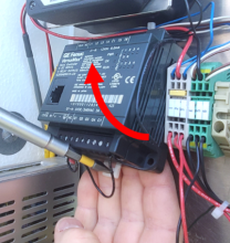
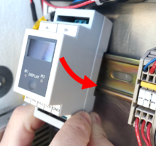
8338 - 8337 - Remove LD-260; Remark:8336
8337 - Remove LD-260
Remove LD-260
8336 - Retain part for reinstallation
Retain part for reinstallation
8351 - 8350 - Uninstall RS232 to RS485 converter; Remark:
8350 - Uninstall RS232 to RS485 converter
Uninstall RS232 to RS485 converter
8349 - 7293 - Disconnect RJ-45 Ethernet cable; Remark:8367
5291 - Note : It is good practice to verify all cables and connectors are labeled prior to ...
It is good practice to verify all cables and connectors are labeled prior to disconnection.
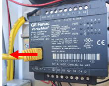
7293 - Disconnect RJ-45 Ethernet cable
Disconnect RJ-45 Ethernet cable
8367 -
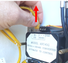
8354 - 8353 - Disconnect power/signal connector; Remark:8352
8353 - Disconnect power/signal connector
Disconnect power/signal connector
8352 - Needle nose pliers may be used
Needle nose pliers may be used
8358 - 8357 - Remove mounting hardware; Remark:8356
8357 - Remove mounting hardware
Remove mounting hardware
8356 - For a VM-250, use Pliers. Retain hardware. For a TM-850, remove mounti...
For a VM-250, use Pliers. Retain hardware.
For a TM-850, remove mounting screws. Use medium Phillips (PH2) screwdriver. Retain screws.

8359 - 8355 - Remove RS232 to RS485 converter; Remark:
8355 - Remove RS232 to RS485 converter
Remove RS232 to RS485 converter
8366 - 8364 - Label component; Remark:8363
8365 - Note : This component is no longer required.
This component is no longer required.
8364 - Label component
Label component
8363 - Use a tag or tape. Include date of removal, description of failure symptoms, ...
Use a tag or tape. Include date of removal, description of failure symptoms, country, site, and lane number. Retain or dispose of component per Nuclear Smuggling Detection and Deterrence (NSDD) guidance or contractual requirements.
8362 - 8361 - Uninstall Nano Controller; Remark:
8361 - Uninstall Nano Controller
Uninstall Nano Controller
8370 - 8369 - Disconnect RJ-45 Ethernet cable; Remark:8368
5291 - Note : It is good practice to verify all cables and connectors are labeled prior to ...
It is good practice to verify all cables and connectors are labeled prior to disconnection.
8369 - Disconnect RJ-45 Ethernet cable
Disconnect RJ-45 Ethernet cable
8368 -
8377 - 8376 - Disconnect occupancy sensor wires; Remark:8375
8376 - Disconnect occupancy sensor wires
Disconnect occupancy sensor wires
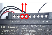
8375 - Use small slotted screwdriver. Remove wires from I1 terminal...
Use small slotted screwdriver. Remove wires from I1 terminal and I2 terminal.
8378 - 8374 - Disconnect power wires; Remark:8373
8374 - Disconnect power wires
Disconnect power wires
8373 - These wires go to Terminal Block 1 (TB1). Use small slotted screwdriver
These wires go to Terminal Block 1 (TB1). Use small slotted screwdriver

8379 - 8372 - Disconnect occupancy output wire; Remark:8371
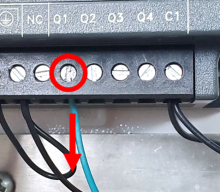
8372 - Disconnect occupancy output wire
Disconnect occupancy output wire
8371 - Use small slotted screwdriver. Remove green wire from Q1 ter...
Use small slotted screwdriver. Remove green wire from Q1 terminal.
8383 - 8381 - Remove Nano Controller; Remark:8380
8382 - Note : Nano Controller installation may differ from configuration shown in this proc...
Nano Controller installation may differ from configuration shown in this procedure.
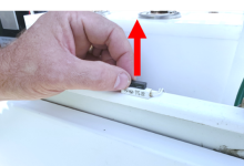
8381 - Remove Nano Controller
Remove Nano Controller
8380 - Use slotted screwdriver to pull down tab and rotate Nano Controller up. Use m...
Use slotted screwdriver to pull down tab and rotate Nano Controller up. Use medium Phillips (PH2) screwdriver if Nano Controller is mounted with screws.
8398 - 8396 - Label component; Remark:8395
8397 - Note : This component is no longer required
This component is no longer required
8396 - Label component
Label component
8395 - Use a tag or tape. Include date of removal, description of failure symptoms, ...
Use a tag or tape. Include date of removal, description of failure symptoms, country, site, and lane number. Retain or dispose of component per NSDD guidance or contractual requirements.
8394 - 8393 - Install ThetaController; Remark:
8393 - Install ThetaController
Install ThetaController
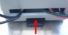
8390 - 8389 - Lower mounting tab; Remark:8388
8403 - Note : Depending on the RPM configuration, it may be easier to attach the ThetaContr...
Depending on the RPM configuration, it may be easier to attach the ThetaController to the mounting rail after all wiring is complete.
8389 - Lower mounting tab
Lower mounting tab
8388 - The tab on the back of the ThetaController must be in the DOWN position to in...
The tab on the back of the ThetaController must be in the DOWN position to install on the mounting rail.

8391 - 8387 - Set ThetaController in place; Remark:8386
8387 - Set ThetaController in place
Set ThetaController in place
8386 - Hook ThetaController to top of mounting rail and rotate down.
Hook ThetaController to top of mounting rail and rotate down.
8392 - 8385 - Lock mounting tab; Remark:8384
8385 - Lock mounting tab
Lock mounting tab
8384 - On bottom of ThetaController, push tab up to lock into place.
On bottom of ThetaController, push tab up to lock into place.
8404 - 8402 - Connect speed output wire to B+ terminal; Remark:8401
5553 - Caution : Correct placement of connectors and wiring is critical to proper operation.
Correct placement of connectors and wiring is critical to proper operation.
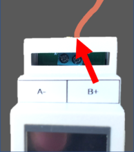
8402 - Connect speed output wire to B+ terminal
Connect speed output wire to B+ terminal
8401 - Remove wire from (+) terminal on RS232 to RS485 converter power/signal connec...
Remove wire from (+) terminal on RS232 to RS485 converter power/signal connector (usually orange color). The other end of this wire connects to terminal block 3 (TB3) at position 9. Use small slotted screwdriver to tighten wiring connections.
8405 - 8400 - Connect speed output wire to A- terminal; Remark:8399
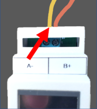
8400 - Connect speed output wire to A- terminal
Connect speed output wire to A- terminal
8399 - Remove wire from (-) terminal on RS232 to RS485 converter power/signal connec...
Remove wire from (-) terminal on RS232 to RS485 converter power/signal connector (usually yellow color). The other end of this wire connects to TB3, position 10. Use small slotted screwdriver to tighten wiring connections

8415 - 8411 - Connect occupancy input to IR1 terminal; Remark:8410
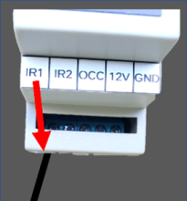
8411 - Connect occupancy input to IR1 terminal
Connect occupancy input to IR1 terminal
8410 - Use wire from I1 terminal on Nano Controller (usually black color). This wire...
Use wire from I1 terminal on Nano Controller (usually black color). This wire comes from the black infrared occupancy sensor.
8416 - 8409 - Connect occupancy input to IR2 terminal; Remark:8408
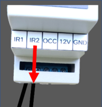
8409 - Connect occupancy input to IR2 terminal
Connect occupancy input to IR2 terminal
8408 - Use wire from I2 terminal on Nano Controller (usually black color). This wire...
Use wire from I2 terminal on Nano Controller (usually black color). This wire comes from the yellow infrared occupancy sensor.
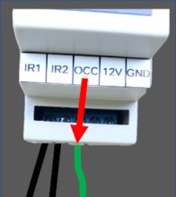
8417 - 8407 - Connect occupancy output to OCC terminal; Remark:8406
8407 - Connect occupancy output to OCC terminal
Connect occupancy output to OCC terminal
8406 - Use wire from Q1 terminal on Nano Controller (usually green color). The other...
Use wire from Q1 terminal on Nano Controller (usually green color). The other end of this wire connects to TB2, position 6.
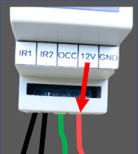
8422 - 8419 - Connect power wire to 12V terminal; Remark:8418
8419 - Connect power wire to 12V terminal
Connect power wire to 12V terminal
8418 - Use wire from 12 VDC IN (+) terminal on the Nano Controller (usually red colo...
Use wire from 12 VDC IN (+) terminal on the Nano Controller (usually red color). The other end of this wire connects to TB2 between positions 16 and 20, which are all +12 VDC.
8423 - 8421 - Connect ground wire to GND terminal; Remark:8420
8421 - Connect ground wire to GND terminal
Connect ground wire to GND terminal
8420 - Use wire from 12 VDC IN (-) terminal on the Nano Controller (usually red colo...
Use wire from 12 VDC IN (-) terminal on the Nano Controller (usually red color). The other end of this wire connects to TB2 between positions 10 and 15, which are all grounded.


7279 - 7249 - Return equipment to normal operating condition; Remark:
7249 - Return equipment to normal operating condition
Return equipment to normal operating condition
7280 - 7250 - Power on RPM; Remark:7251
7250 - Power on RPM
Power on RPM
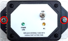
7251 - Move LD-260 switch to ON position. The LED PWR ON
Move LD-260 switch to ON position. The LED PWR ON will illuminate.
7468 - 7304 - Confirm RPM has restarted correctly; Remark:7487
7304 - Confirm RPM has restarted correctly
Confirm RPM has restarted correctly
7487 - The SC-770 controller will display "OK" following Power On Self-Test (POST) a...
The SC-770 controller will display "OK" following Power On Self-Test (POST) and background measurement.
7282 - 7254 - Confirm network connection; Remark:7255
7254 - Confirm network connection
Confirm network connection
7255 - Contact operators to confirm communications have been reestablished between RPM ...
8317 - 8316 - Enable both infrared occupancy sensors; Remark:8315
7263 - Caution : Correct placement of connectors and wiring is critical to proper operation.
Correct placement of connectors and wiring is critical to proper operation.
8316 - Enable both infrared occupancy sensors
Enable both infrared occupancy sensors
8315 - To reconnect sensor cable, align connectors, push towards sensor, and turn th...
To reconnect sensor cable, align connectors, push towards sensor, and turn the collar clockwise.
8433 - 8432 - Close all RPM doors; Remark:
8432 - Close all RPM doors
Close all RPM doors
8434 - 8431 - Generate speed message; Remark:8430
8431 - Generate speed message
Generate speed message
8430 - Stand to side of control pillar. Open door with infrared sensors.
Stand to side of control pillar. Open door with infrared sensors.

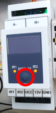
8435 - 8429 - Verify ThetaController response; Remark:8428
8429 - Verify ThetaController response
Verify ThetaController response
8428 - IR1 and IR2 will be illuminated
IR1 and IR2 will be illuminated

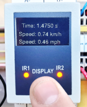
8436 - 8427 - Check speed value; Remark:8426
8427 - Check speed value
Check speed value
8426 - Press button to display speed information for latest occupancy on ThetaContro...
Press button to display speed information for latest occupancy on ThetaController.
8437 - 8425 - Verify speed message in CAS; Remark:8424
8425 - Verify speed message in CAS
Verify speed message in CAS
8424 - Contact CAS operator to verify “SP” appears in RAVEN [Radiation Alarm and...
Contact CAS operator to verify “SP” appears in RAVEN [Radiation Alarm and Video Event Notification] data stream and/or the daily file. Speed messages can also be viewed by connecting a computer to the SC-770 Ethernet output.
8318 - 7450 - Enable tamper switches; Remark:7348
7450 - Enable tamper switches
Enable tamper switches
7348 - Remove all magnets and/or adhesive tape from door switches.
Remove all magnets and/or adhesive tape from door switches.
7283 - 7256 - Close and lock all RPM doors; Remark:
7256 - Close and lock all RPM doors
Close and lock all RPM doors
7842 - 7820 - Inform system operators upon completion of maintenance action; Remark:
7820 - Inform system operators upon completion of maintenance action
Inform system operators upon completion of maintenance action
322 - 321 - Bakım İşlemlerini kaydedin; Remark:
321 - Bakım İşlemlerini kaydedin
Bakım İşlemlerini kaydedin
2869 - 2585 - Yapılan bakımı kaydedin; Remark:2866
2585 - Yapılan bakımı kaydedin
Yapılan bakımı kaydedin
2866 - Düzeltici Bakım Raporu için gözlemleri, zamanları ve sonuçları kaydedin.
Düzeltici Bakım Raporu için gözlemleri, zamanları ve sonuçları kaydedin.
4706 - 4705 - Submit report; Remark:4864
4705 - Submit report
Submit report
4864 - As specified by management or contractual obligations.
As specified by management or contractual obligations.