Last Updated: 04/24/2025 1:42 AM
The following table lists all the components that make up the document.
Replace the RadSeeker CS stabilization module. Several steps will need to be performed using the NSDD (Nuclear Smuggling Detection and Deterrence) Maintenance Toolbox (NMT), available from the NSDD Program. The user must have familiarity with NMT to perform the tasks and complete this procedure.
Prior to arrival, notify operators concerning expected work and duration.
Added steps to use NSDD Maintenance Toolbox (NMT) 4.0 software instead of HATS. Included all disassembly steps for clarity. Modified steps to remove detector assembly without the need to cut wire ties.
5356 - 5355 - Backup RadSeeker Files; Remark:
5355 - Backup RadSeeker Files
Backup RadSeeker Files
4745 - 220 - Power on instrument; Remark:4729
220 - Power on instrument
Power on instrument
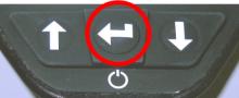
4729 - Press and hold ENTER button until display powers on (3 to 5 ...
Press and hold ENTER button until display powers on (3 to 5 seconds).
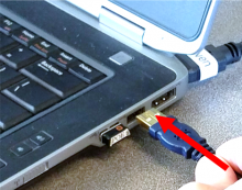
3690 - 3601 - Connect instrument to computer; Remark:5972
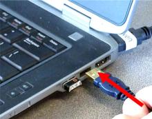
3601 - Connect instrument to computer
Connect instrument to computer

5373 - 5371 - Backup file structure; Remark:10751
5371 - Backup file structure
Backup file structure
10751 - Use NMT to perform this step.
Use NMT to perform this step.
10753 - It is recommended to backup the file structure, but not necessary. ...
It is recommended to backup the file structure, but not necessary.
At a minimum, the Calibration History file should be saved prior to performing this procedure.
The backup might take up to 30 minutes.
3700 - 3591 - Disconnect instrument from computer; Remark:3622
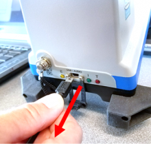
3591 - Disconnect instrument from computer
Disconnect instrument from computer
2497 - 313 - Power off instrument; Remark:2330
313 - Power off instrument
Power off instrument
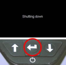
2330 - Press ENTER until the screen displays Shutting down
Press ENTER until the screen displays Shutting down.
5017 - 5016 - Disassemble Enclosure; Remark:
5016 - Disassemble Enclosure
Disassemble Enclosure
5271 - 5270 - Remove battery; Remark:5269
5270 - Remove battery
Remove battery
5269 - Unclasp battery door. Open battery door. Use tab to pull battery. Close and r...
Unclasp battery door. Open battery door. Use tab to pull battery. Close and reclasp battery door after removal.

5278 - 5277 - Orient RadSeeker; Remark:5276
5277 - Orient RadSeeker
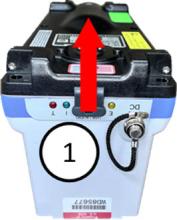
Orient RadSeeker
5276 - Rotate RadSeeker to expose underside and bumpers.
Rotate RadSeeker to expose underside and bumpers.
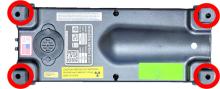
5281 - 5280 - Loosen eight (8) bumper screws; Remark:5279
5280 - Loosen eight (8) bumper screws
Loosen eight (8) bumper screws
5279 - Use small Phillips (PH1) screwdriver. Each bumper contains two (2) screws for...
Use small Phillips (PH1) screwdriver. Each bumper contains two (2) screws for a total of eight (8) screws. Retain screws within bumpers.
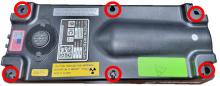
5284 - 5283 - Remove six (6) enclosure screws; Remark:5282
5288 - Note : Enclosure screws might be Phillips (PH2) or T4 Torx.
Enclosure screws might be Phillips (PH2) or T4 Torx.
5283 - Remove six (6) enclosure screws
Remove six (6) enclosure screws
5282 - Use medium Phillips (PH2) screwdriver (or T4 Torx screwdriver if applicable)....
Use medium Phillips (PH2) screwdriver (or T4 Torx screwdriver if applicable). Retain screws.
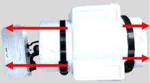
5287 - 5286 - Remove bottom cover; Remark:5285
5286 - Remove bottom cover
Remove bottom cover
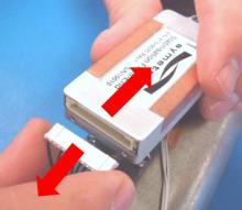
5285 - Lift vertically. Rotate cover. Set cover down on same side as cable connectio...
Lift vertically. Rotate cover. Set cover down on same side as cable connection.

5292 - 5290 - Disconnect beeper; Remark:5289
1345 - Note : It is good practice to ensure all cables and connectors are labeled prior to ...
It is good practice to ensure all cables and connectors are labeled prior to disconnection.
5290 - Disconnect beeper
Disconnect beeper
5289 - Use needle nose pliers. Pull connector directly away from circuit board. ...
Use needle nose pliers. Pull connector directly away from circuit board.

5015 - 5014 - Uninstall Processor PCB; Remark:
5293 - Caution : An electrostatic discharge wrist-strap should be worn to prevent damage to el...
An electrostatic discharge wrist-strap should be worn to prevent damage to electronic components.
5014 - Uninstall Processor PCB
Uninstall Processor PCB
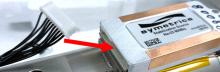
5295 - 5294 - Disconnect Wi-Fi antenna; Remark:5289
1345 - Note : It is good practice to ensure all cables and connectors are labeled prior to ...
It is good practice to ensure all cables and connectors are labeled prior to disconnection.
5294 - Disconnect Wi-Fi antenna
Disconnect Wi-Fi antenna
5289 - Use needle nose pliers. Pull connector directly away from circuit board. ...
Use needle nose pliers. Pull connector directly away from circuit board.

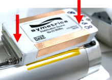
5298 - 5297 - Remove four (4) processor PCB screws; Remark:5296
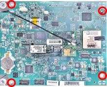
5297 - Remove four (4) processor PCB screws
Remove four (4) processor PCB screws
5296 - Use small Phillips (PH1) screwdriver. Retain screws.
Use small Phillips (PH1) screwdriver. Retain screws.
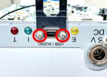
5301 - 5300 - Remove two (2) USB dust cover screws; Remark:5299
5300 - Remove two (2) USB dust cover screws
Remove two (2) USB dust cover screws
5299 - Use very small Phillips (PH0) screwdriver. Retain screws, washers and dust co...
Use very small Phillips (PH0) screwdriver. Retain screws, washers and dust cover.
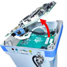
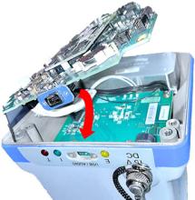
5304 - 5302 - Lift processor PCB; Remark:5331
5303 - Caution : Wiring and cables are still connected to the underside of the component. ...
Wiring and cables are still connected to the underside of the component.
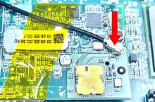
5302 - Lift processor PCB
Lift processor PCB
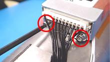
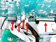
5307 - 5306 - Disconnect five (5) processor PCB cables; Remark:5305
1345 - Note : It is good practice to ensure all cables and connectors are labeled prior to ...
It is good practice to ensure all cables and connectors are labeled prior to disconnection.
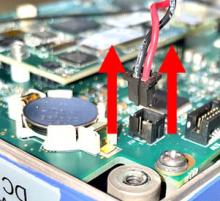
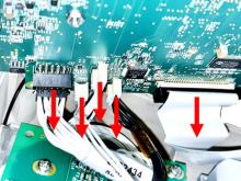
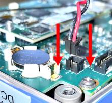
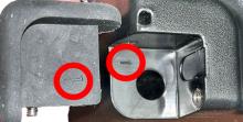
5306 - Disconnect five (5) processor PCB cables
Disconnect five (5) processor PCB cables
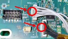
5305 - Push in the tabs of the two (2) connectors with this feature.
Push in the tabs of the two (2) connectors with this feature.
5332 - Pull connectors directly away from circuit board. Set aside processor PCB.
Pull connectors directly away from circuit board. Set aside processor PCB.
5003 - 5002 - Uninstall Gamma Detector Assembly; Remark:
5002 - Uninstall Gamma Detector Assembly
Uninstall Gamma Detector Assembly
5317 - 5316 - Remove four (4) gamma detector screws; Remark:5315
5316 - Remove four (4) gamma detector screws
Remove four (4) gamma detector screws
5315 - Use medium Phillips (PH2) screwdriver. Retain screws.
Use medium Phillips (PH2) screwdriver. Retain screws.
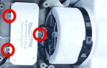
5319 - 5318 - Remove three (3) MCA screws; Remark:5296
5318 - Remove three (3) MCA screws
Remove three (3) MCA screws
5296 - Use small Phillips (PH1) screwdriver. Retain screws.
Use small Phillips (PH1) screwdriver. Retain screws.
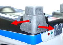
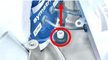
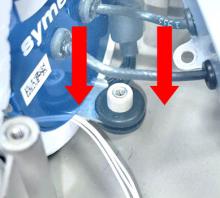
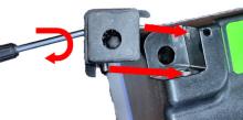
5340 - 5339 - Remove mounting bracket tab; Remark:5338
5339 - Remove mounting bracket tab
Remove mounting bracket tab
5338 - Carefully pry grommet off of mounting post.
Carefully pry grommet off of mounting post.
5341 - 5337 - Remove gamma detector assembly; Remark:5336
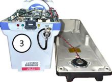
5337 - Remove gamma detector assembly
Remove gamma detector assembly
5336 - Simultaneously lift the MCA and gamma detector and set aside.
Simultaneously lift the MCA and gamma detector and set aside.
5354 - 5353 - Disassemble Gamma Detector Assembly; Remark:
5353 - Disassemble Gamma Detector Assembly
Disassemble Gamma Detector Assembly
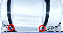
10758 - 10757 - Remove Wire Ties; Remark:10755
10757 - Remove Wire Ties
Remove Wire Ties
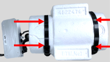
10755 - Slide wire ties off of styrofoam surround. It might be necessary to compress ...
Slide wire ties off of styrofoam surround. It might be necessary to compress the styrofoam to allow removal.
5393 - 5387 - Remove Styrofoam covers; Remark:5519
5387 - Remove Styrofoam covers
Remove Styrofoam covers
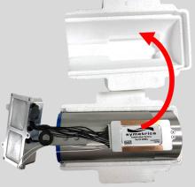
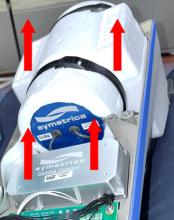
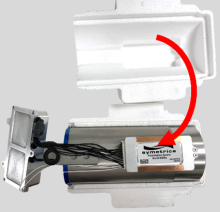
5394 - 5386 - Orient gamma detector; Remark:5385
5386 - Orient gamma detector
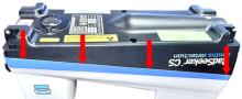
Orient gamma detector
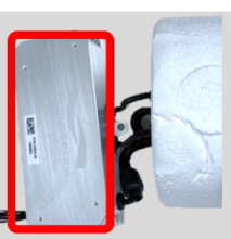
5385 - The stabilization module will be on the top.
The stabilization module will be on the top.
5352 - 5351 - Uninstall Expired Stabilization Module; Remark:
5351 - Uninstall Expired Stabilization Module
Uninstall Expired Stabilization Module
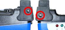
5399 - 5405 - Remove two (2) mounting screws; Remark:5398
5405 - Remove two (2) mounting screws
Remove two (2) mounting screws
5398 - Use T6 Torx screwdriver. Retain screws.
Use T6 Torx screwdriver. Retain screws.
5400 - 5396 - Disconnect the MCA [multi-channel analyzer] cable connector from the stabiliz...; Remark:5531
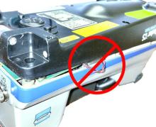
5397 - Warning : Do not disassemble the stabilization source module. The expired stabilization...
Do not disassemble the stabilization source module. The expired stabilization module still contains low level amounts of radioactive Sodium-22 (Na-22). Dispose of the expired stabilization module per local regulations.
5396 - Disconnect the MCA [multi-channel analyzer] cable connector from the stabiliz...
Disconnect the MCA [multi-channel analyzer] cable connector from the stabilization module
3397 - 3395 - Arızalı bileşeni etiketleyin; Remark:3396
3395 - Arızalı bileşeni etiketleyin
Arızalı bileşeni etiketleyin
3396 - Etiket veya bant kullanın. Çıkarıldığı tarihi, arıza belirtilerinin açıklamasını...
Etiket veya bant kullanın. Çıkarıldığı tarihi, arıza belirtilerinin açıklamasını, ülkeyi, sahayı ve şerit numarasını ekleyin. Nükleer Kaçakçılık Tespiti ve Caydırıcılık (NSDD) kılavuzuna veya sözleşme gereksinimlerine göre imha edin.
5350 - 5349 - Yeni Stabilizasyon Modülünü takın; Remark:
5349 - Yeni Stabilizasyon Modülünü takın
Yeni Stabilizasyon Modülünü takın
5428 - 5427 - Place new stabilization module on mounting bracket; Remark:10782
5427 - Place new stabilization module on mounting bracket
Place new stabilization module on mounting bracket
5430 - 5425 - Reinstall two (2) mounting screws; Remark:5424
569 - Caution : Do not overtighten screws.
Do not overtighten screws.
5431 - Standard : Torque screws to 2 in-lbs. (inch-pounds).
Torque screws to 2 in-lbs. (inch-pounds).
5425 - Reinstall two (2) mounting screws
Reinstall two (2) mounting screws
5424 - Use T6 Torx screwdriver.
Use T6 Torx screwdriver.

5429 - 5426 - Connect MCA to stabilization module; Remark:5530
5426 - Connect MCA to stabilization module
Connect MCA to stabilization module
5348 - 5347 - Reinstall Gamma Detector Assembly; Remark:
5347 - Reinstall Gamma Detector Assembly
Reinstall Gamma Detector Assembly
10770 - 10761 - Replace Styrofoam casing; Remark:10759
10761 - Replace Styrofoam casing
Replace Styrofoam casing
10759 - There is a cutout for the stabilization module in one piece of the styrofoam ...
There is a cutout for the stabilization module in one piece of the styrofoam casing.
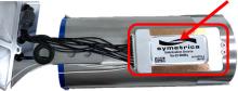
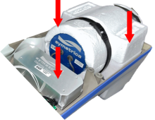
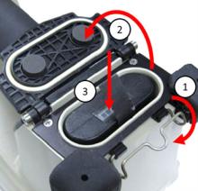
10776 - 10775 - Orient detector assembly; Remark:10765
10775 - Orient detector assembly
Orient detector assembly
10765 - Place the detector assembly with the stabilization module facing down. The mu...
Place the detector assembly with the stabilization module facing down. The multi-channel analyzer should be facing up with the Symetrica logo visible.
10771 - 10769 - Replace wire ties; Remark:10767
10769 - Replace wire ties
Replace wire ties
10767 - Slide wire ties on to styrofoam casing.
Slide wire ties on to styrofoam casing.
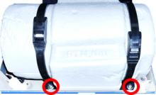
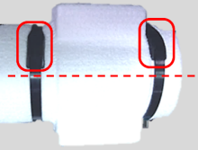
10772 - 10764 - Verify wire tie orientation; Remark:10762
10764 - Verify wire tie orientation
Verify wire tie orientation
10762 - Align wire ties with mounting tabs on bottom. Verify wire tie connection is ...
Align wire ties with mounting tabs on bottom. Verify wire tie connection is offset from centerline so that detector assembly will fit into enclosure.
5485 - 5484 - Insert detector and MCA; Remark:5483
5484 - Insert detector and MCA
Insert detector and MCA
5483 - The detector is placed with the stabilization module facing down.
The detector is placed with the stabilization module facing down.
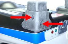
5486 - 5481 - Reseat mounting tab; Remark:5480
5482 - Caution : Direct pressure to the metal mounting tab will cause damage. Push down evenly...
Direct pressure to the metal mounting tab will cause damage. Push down evenly ONLY on the rubber grommet.
5481 - Reseat mounting tab
Reseat mounting tab
5480 - Secure grommet over mounting post using even pressure on both sides of the mo...
Secure grommet over mounting post using even pressure on both sides of the mounting grommet.
5489 - 5475 - Reinstall three (3) MCA mounting screws; Remark:5474
569 - Caution : Do not overtighten screws.
Do not overtighten screws.
5490 - Standard : Torque MCA screws to 4 in-lbs.
Torque MCA screws to 4 in-lbs.
5475 - Reinstall three (3) MCA mounting screws
Reinstall three (3) MCA mounting screws
5474 - Use small Phillips (PH1) screwdriver.
Use small Phillips (PH1) screwdriver.
5528 - 5523 - Replace four (4) gamma detector mounting screws; Remark:5521
569 - Caution : Do not overtighten screws.
Do not overtighten screws.
5467 - Standard : Torque gamma detector screws to 7 in-lbs.
Torque gamma detector screws to 7 in-lbs.
5523 - Replace four (4) gamma detector mounting screws
Replace four (4) gamma detector mounting screws
5521 - Use medium Phillips (PH2) screwdriver.
Use medium Phillips (PH2) screwdriver.
5009 - 5008 - Reinstall Processor PCB; Remark:
5008 - Reinstall Processor PCB
Reinstall Processor PCB
5554 - 5552 - Reconnect five (5) cables to underside of processor PCB; Remark:5551
5553 - Caution : Correct placement of connectors and wiring is critical to proper operation.
Correct placement of connectors and wiring is critical to proper operation.
5552 - Reconnect five (5) cables to underside of processor PCB
Reconnect five (5) cables to underside of processor PCB
5555 - 5550 - Insert processor PCB; Remark:5549
5550 - Insert processor PCB
Insert processor PCB
5549 - Fit USB interface into chassis cutout, then lower in processor PCB.
Fit USB interface into chassis cutout, then lower in processor PCB.
5556 - 5547 - Replace two (2) USB dust cover screws; Remark:5545
569 - Caution : Do not overtighten screws.
Do not overtighten screws.
5548 - Standard : Torque USB dust cover screws to 1.6 in-lbs
Torque USB dust cover screws to 1.6 in-lbs
5547 - Replace two (2) USB dust cover screws
Replace two (2) USB dust cover screws
5545 - Use very small Phillips (PH0) screwdriver.
Use very small Phillips (PH0) screwdriver.
5557 - 5544 - Reconnect Wi-Fi cable; Remark:5543
5544 - Reconnect Wi-Fi cable
Reconnect Wi-Fi cable
5543 - Push connector directly toward circuit board.
Push connector directly toward circuit board.
5007 - 5006 - Reassemble Enclosure; Remark:
5006 - Reassemble Enclosure
Reassemble Enclosure
5565 - 5564 - Reconnect beeper cable; Remark:5562
5564 - Reconnect beeper cable
Reconnect beeper cable
5562 - Connector should click securely into place.
Connector should click securely into place.
5566 - 5560 - Replace bottom cover; Remark:5558
5561 - Caution : Verify the silicone tube O-ring does not become pinched or d...
Verify the silicone tube O-ring does not become pinched or damaged when joining enclosures.
5895 - Caution : Verify all wiring is inside the instrument while replacing cover.
Verify all wiring is inside the instrument while replacing cover.
5560 - Replace bottom cover
Replace bottom cover
5558 - Avoid damage to the internal O-ring.
Avoid damage to the internal O-ring.

5559 - Enclosures should fit snugly together.
Enclosures should fit snugly together.
5571 - 5569 - Replace six (6) enclosure screws; Remark:5567
569 - Caution : Do not overtighten screws.
Do not overtighten screws.
5570 - Standard : Torque screws to 7 in-lbs.
Torque screws to 7 in-lbs.
5569 - Replace six (6) enclosure screws
Replace six (6) enclosure screws
5567 - If available, use torque screwdriver set to 7 in-lbs. with medium Phillips (P...
If available, use torque screwdriver set to 7 in-lbs. with medium Phillips (PH2) screwdriver bit.
5574 - 5573 - Verify bumpers are positioned correctly.; Remark:5572
5573 - Verify bumpers are positioned correctly.
Verify bumpers are positioned correctly.
5572 - Each foot and matching bumper should have identifying marks.
Each foot and matching bumper should have identifying marks.
5577 - 5576 - Tighten eight (8) bumper screws; Remark:5575
5576 - Tighten eight (8) bumper screws
Tighten eight (8) bumper screws
5575 - Use small Phillips (PH1) screwdriver. Each bumper contains two (2) screws for...
Use small Phillips (PH1) screwdriver. Each bumper contains two (2) screws for a total of eight (8) screws. Verify screws are secure.
5580 - 10484 - Insert battery pack; Remark:5578
10484 - Insert battery pack
Insert battery pack
5578 - Unclasp battery latch. Open battery latch. Reinsert battery.
Unclasp battery latch. Open battery latch. Reinsert battery.

5346 - 5345 - Perform Setup; Remark:
5345 - Perform Setup
Perform Setup
4745 - 220 - Power on instrument; Remark:4729
220 - Power on instrument
Power on instrument
4729 - Press and hold ENTER button until display powers on (3 to 5 ...
Press and hold ENTER button until display powers on (3 to 5 seconds).
4778 - 3601 - Connect instrument to computer; Remark:4830
3601 - Connect instrument to computer
Connect instrument to computer
5441 - 5437 - Update Calibration History File; Remark:10751
5437 - Update Calibration History File
Update Calibration History File
10751 - Use NMT to perform this step.
Use NMT to perform this step.
10754 - Update the Calibration History File with the current stabilization module rep...
Update the Calibration History File with the current stabilization module replacement date.
5442 - 5435 - Perform RadSeeker Calibration (optional); Remark:5434
5435 - Perform RadSeeker Calibration (optional)
Perform RadSeeker Calibration (optional)
5434 - If a europium-152 (Eu-152) source is available, perform calibration procedure...
If a europium-152 (Eu-152) source is available, perform calibration procedure.
DET-HHD-SMD-RSK-CM03, RadSeeker Calibration
5443 - 319 - Perform operational test; Remark:5432
319 - Perform operational test
Perform operational test
5432 - To perform an operational test, refer to DET-HHD-SMD-RSK-RM01, RadS...
To perform an operational test, refer to
DET-HHD-SMD-RSK-RM01, RadSeeker Operational Test
322 - 321 - Bakım İşlemlerini kaydedin; Remark:
321 - Bakım İşlemlerini kaydedin
Bakım İşlemlerini kaydedin
2869 - 2585 - Yapılan bakımı kaydedin; Remark:2866
2585 - Yapılan bakımı kaydedin
Yapılan bakımı kaydedin
2866 - Düzeltici Bakım Raporu için gözlemleri, zamanları ve sonuçları kaydedin.
Düzeltici Bakım Raporu için gözlemleri, zamanları ve sonuçları kaydedin.
4706 - 4705 - Submit report; Remark:4864
4705 - Submit report
Submit report
4864 - As specified by management or contractual obligations.
As specified by management or contractual obligations.