| Sensor Tech TA600 Radiation Pager |
Device
|
Published
|
10/28/2024 3:51 PM
|
| 7500 - 7489 - Remove existing battery; Remark: |
Procedure Step
|
Published
|
04/08/2025 4:30 PM
|
| 7489 - Remove existing battery |
Instruction
|
Published
|
06/03/2023 12:16 AM
|
| 11095 - 313 - Power off instrument; Remark:11093 |
Procedure Step
|
Published
|
10/01/2024 3:33 PM
|
| 313 - Power off instrument |
Instruction
|
Published
|
07/23/2021 2:41 PM
|
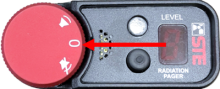
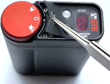
| 11093 - Rotate switch to OFF position. |
Remark
|
Published
|
10/01/2024 3:29 PM
|
| 11094 - TA600 Rotate switch to OFF Position |
Remark
|
Published
|
10/01/2024 3:33 PM
|
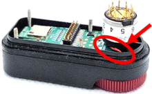
| 11204 - 4370 - Locate battery cover; Remark:11202 |
Procedure Step
|
Published
|
10/01/2024 10:17 PM
|
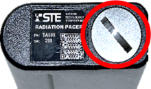
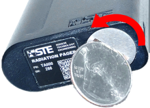
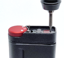
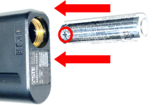
| 4370 - Locate battery cover |
Instruction
|
Published
|
06/06/2022 9:11 PM
|
| 11202 - TA600 Locate battery cover |
Remark
|
Published
|
10/01/2024 10:16 PM
|
| 4369 - 4368 - Remove battery cover; Remark:11198 |
Procedure Step
|
Published
|
06/06/2022 9:13 PM
|
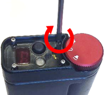
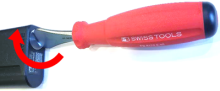
| 4368 - Remove battery cover |
Instruction
|
Published
|
06/06/2022 9:13 PM
|
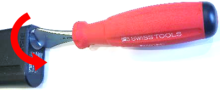
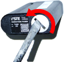
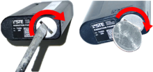
| 11198 - Use a coin screwdriver, a medium #2 slotted screwdriver or a coin. Rotate counte... |
Remark
|
Published
|
10/01/2024 10:19 PM
|
| 11199 - TA600 Use a coin screwdriver, rotate counterclockwise |
Remark
|
Published
|
10/01/2024 10:22 PM
|
| 11200 - TA600 Remove battery cover, rotate counterclockwise |
Remark
|
Published
|
10/01/2024 10:23 PM
|
| 11201 - TA600 Use coin, rotate counterclockwise |
Remark
|
Published
|
10/01/2024 10:25 PM
|
| 11205 - 1816 - Remove battery; Remark:11196 |
Procedure Step
|
Published
|
10/01/2024 10:28 PM
|
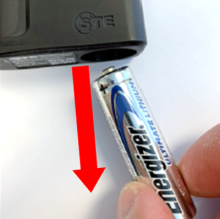
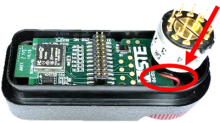
| 1816 - Remove battery |
Instruction
|
Published
|
11/20/2020 9:29 AM
|
| 11196 - Retain battery. |
Remark
|
Published
|
10/01/2024 10:26 PM
|
| 11197 - TA600 Remove battery |
Remark
|
Published
|
10/01/2024 10:27 PM
|
| 11195 - 11194 - Remove faulty top housing; Remark: |
Procedure Step
|
Published
|
10/01/2024 10:29 PM
|
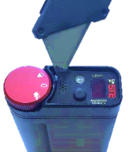
| 11194 - Remove faulty top housing |
Instruction
|
Published
|
10/01/2024 10:28 PM
|
| 11187 - 11185 - Remove label; Remark:11182 |
Procedure Step
|
Published
|
10/01/2024 10:33 PM
|
| 11186 - Caution : Do not mix components or circuit boards between instruments. Some components con... |
Annotation
|
Published
|
10/01/2024 10:29 PM
|
| 11185 - Remove label |
Instruction
|
Published
|
10/01/2024 10:30 PM
|
| 11182 - Use tweezers or a sharp blade to pry up the label using the speaker holes or ... |
Remark
|
Published
|
10/01/2024 10:30 PM
|
| 11183 - TA600 Remove label with tweezers |
Remark
|
Published
|
10/01/2024 10:32 PM
|
| 11184 - TA600 Remove label with sharp blade |
Remark
|
Published
|
10/01/2024 10:33 PM
|
| 11188 - 11181 - Remove four enclosure screws and washers; Remark:11178 |
Procedure Step
|
Published
|
10/01/2024 10:37 PM
|
| 11181 - Remove four enclosure screws and washers |
Instruction
|
Published
|
10/01/2024 10:33 PM
|
| 11178 - Use 0.05-in. hex driver. Retain screws and washers. Washers might be difficult t... |
Remark
|
Published
|
10/01/2024 10:34 PM
|
| 11179 - TA600 Remove four screws |
Remark
|
Published
|
10/01/2024 10:35 PM
|
| 11180 - TA600 Retain screws and washers |
Remark
|
Published
|
10/01/2024 10:37 PM
|
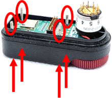
| 11189 - 6177 - Separate top and bottom enclosures; Remark:11176 |
Procedure Step
|
Published
|
10/01/2024 10:39 PM
|
| 11177 - Caution : Wires are still connected. Do not strain black and red wires. They can easily br... |
Annotation
|
Published
|
10/01/2024 10:37 PM
|
| 6177 - Separate top and bottom enclosures |
Instruction
|
Published
|
11/19/2022 5:55 PM
|
| 11176 - TA600 Separate top and bottom enclosures |
Remark
|
Published
|
10/01/2024 10:39 PM
|
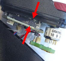
| 11190 - 11174 - Disconnect rotary switch board; Remark:11172 |
Procedure Step
|
Published
|
10/01/2024 10:45 PM
|
| 11175 - Caution : Avoid bending or breaking switch pins. |
Annotation
|
Published
|
10/01/2024 10:43 PM
|
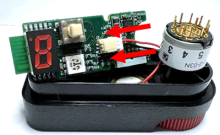
| 11174 - Disconnect rotary switch board |
Instruction
|
Published
|
10/01/2024 10:43 PM
|
| 11172 - Carefully wiggle rotary switch board to remove it from switch. |
Remark
|
Published
|
10/01/2024 10:43 PM
|
| 11173 - TA600 Disconnect rotary switch board |
Remark
|
Published
|
10/01/2024 10:45 PM
|
| 11191 - 11171 - Separate circuit boards; Remark:11169 |
Procedure Step
|
Published
|
10/01/2024 10:48 PM
|
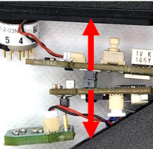
| 11171 - Separate circuit boards |
Instruction
|
Published
|
10/01/2024 10:45 PM
|
| 11169 - Carefully wiggle boards to unplug the socket that holds boards together. |
Remark
|
Published
|
10/01/2024 10:45 PM
|
| 11170 - TA600 Separate circuit boards |
Remark
|
Published
|
10/01/2024 10:46 PM
|
| 11192 - 11168 - Disconnect piezo connector; Remark:11166 |
Procedure Step
|
Published
|
10/01/2024 10:50 PM
|
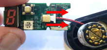
| 11168 - Disconnect piezo connector |
Instruction
|
Published
|
10/01/2024 10:49 PM
|
| 11166 - Retain circuit boards for reinstallation. |
Remark
|
Published
|
10/01/2024 10:49 PM
|
| 11167 - TA600 Disconnect piezo connector |
Remark
|
Published
|
10/01/2024 10:50 PM
|
| 3397 - 3395 - Label faulty component; Remark:3396 |
Procedure Step
|
Published
|
07/21/2024 6:59 AM
|
| 3395 - Label faulty component |
Instruction
|
Published
|
08/07/2021 11:07 AM
|
| 3396 - Use tag or tape. Include date of removal, description of failure symptoms, co... |
Remark
|
Published
|
08/09/2021 11:35 AM
|
| 11162 - 11161 - Install new top housing; Remark: |
Procedure Step
|
Published
|
10/01/2024 10:53 PM
|
| 11161 - Install new top housing |
Instruction
|
Published
|
10/01/2024 10:53 PM
|
| 11156 - 11155 - Connect piezo connector; Remark:11153 |
Procedure Step
|
Published
|
10/01/2024 10:55 PM
|
| 11155 - Connect piezo connector |
Instruction
|
Published
|
10/01/2024 10:54 PM
|
| 11153 - Use new top housing. |
Remark
|
Published
|
10/01/2024 10:54 PM
|
| 11154 - TA600 Use New Top Housing |
Remark
|
Published
|
10/01/2024 10:55 PM
|
| 11157 - 11152 - Insert PCBA into top housing; Remark:11149 |
Procedure Step
|
Published
|
10/01/2024 10:58 PM
|
| 11152 - Insert PCBA into top housing |
Instruction
|
Published
|
10/01/2024 10:55 PM
|
| 11149 - TA600 Insert PCBA into top housing |
Remark
|
Published
|
10/01/2024 10:56 PM
|
| 11150 - Route wires under rotary switch connector. Wires should not be coiled up on piez... |
Remark
|
Published
|
10/01/2024 10:57 PM
|
| 11151 - TA600 Route wires under rotary switch |
Remark
|
Published
|
10/01/2024 10:58 PM
|
| 11158 - 11148 - Insert four enclosure screws and washers; Remark:11145 |
Procedure Step
|
Published
|
10/01/2024 11:01 PM
|
| 11148 - Insert four enclosure screws and washers |
Instruction
|
Published
|
10/01/2024 10:59 PM
|
| 11145 - TA600 Insert four enclosure screws and washers |
Remark
|
Published
|
10/01/2024 11:00 PM
|
| 11146 - Verify screws do not interfere with piezo wires. |
Remark
|
Published
|
10/01/2024 11:00 PM
|
| 11147 - TA600 Verify screws do not interfere with piezo wires |
Remark
|
Published
|
10/01/2024 11:01 PM
|
| 11159 - 11143 - Connect PCBAs; Remark:11141 |
Procedure Step
|
Published
|
10/01/2024 11:05 PM
|
| 11144 - Caution : Verify the connectors are aligned correctly. Misalignment of this connector is c... |
Annotation
|
Published
|
10/01/2024 11:01 PM
|
| 11143 - Connect PCBAs |
Instruction
|
Published
|
10/01/2024 11:02 PM
|
| 11141 - Carefully line up the pins with the sockets and press firmly. |
Remark
|
Published
|
10/01/2024 11:02 PM
|
| 11142 - TA600 Connect PCBAs line up pins with sockets |
Remark
|
Published
|
10/01/2024 11:05 PM
|
| 11160 - 11140 - Connect rotary switch board; Remark:11141 |
Procedure Step
|
Published
|
10/01/2024 11:06 PM
|
| 11140 - Connect rotary switch board |
Instruction
|
Published
|
10/01/2024 11:05 PM
|
| 11237 - TA600 Connect rotary switch board |
Remark
|
Published
|
10/01/2024 11:09 PM
|
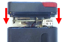
| 11238 - 11235 - Place top housing on bottom housing; Remark:11233 |
Procedure Step
|
Published
|
10/01/2024 11:12 PM
|
| 11236 - Caution : Verify all wires are inside instrument. Verify wires do not interfere ... |
Annotation
|
Published
|
10/01/2024 11:10 PM
|
| 11235 - Place top housing on bottom housing |
Instruction
|
Published
|
10/01/2024 11:10 PM
|
| 11233 - Route wire to avoid enclosure screws. |
Remark
|
Published
|
10/01/2024 11:10 PM
|
| 11234 - TA600 Place top housing, route wire to avoid screws |
Remark
|
Published
|
10/01/2024 11:12 PM
|
| 11239 - 11232 - Evenly tighten enclosure screws; Remark:11228 |
Procedure Step
|
Published
|
10/01/2024 11:18 PM
|
| 569 - Caution : Do not overtighten screws. |
Annotation
|
Published
|
06/16/2021 2:31 PM
|
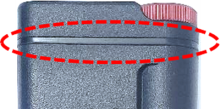
| 11232 - Evenly tighten enclosure screws |
Instruction
|
Published
|
10/01/2024 11:13 PM
|
| 11228 - Evenly tighten screws until the gasket is lightly compressed. It is recommended ... |
Remark
|
Published
|
10/01/2024 11:13 PM
|
| 11229 - TA600 Evenly tighten screws |
Remark
|
Published
|
10/01/2024 11:14 PM
|
| 11230 - TA600 Tighten screws until gasket compressed |
Remark
|
Published
|
10/01/2024 11:16 PM
|
| 11231 - |
Remark
|
Published
|
10/01/2024 11:18 PM
|
| 11240 - 11227 - Verify enclosure screws are tightened correctly; Remark:11225 |
Procedure Step
|
Published
|
10/01/2024 11:20 PM
|
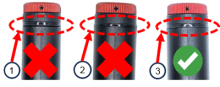
| 11227 - Verify enclosure screws are tightened correctly |
Instruction
|
Published
|
10/01/2024 11:18 PM
|
| 11225 - 1 – Not tight enough; gap between gasket and housing 2 – Too tight... |
Remark
|
Published
|
10/01/2024 11:19 PM
|
| 11226 - TA600 Verify enclosure screws tightened correctly |
Remark
|
Published
|
10/01/2024 11:20 PM
|
| 11224 - 11223 - Replace battery; Remark: |
Procedure Step
|
Published
|
10/01/2024 11:21 PM
|
| 11223 - Replace battery |
Instruction
|
Published
|
10/01/2024 11:21 PM
|
| 11221 - 11220 - Insert battery; Remark:11218 |
Procedure Step
|
Published
|
10/01/2024 11:23 PM
|
| 11220 - Insert battery |
Instruction
|
Published
|
10/01/2024 11:21 PM
|
| 11218 - Insert positive (+) terminal first. |
Remark
|
Published
|
10/01/2024 11:21 PM
|
| 11219 - TA600 Insert battery |
Remark
|
Published
|
10/01/2024 11:22 PM
|
| 11222 - 4354 - Reinstall battery cover; Remark:11215 |
Procedure Step
|
Published
|
10/01/2024 11:28 PM
|
| 4354 - Reinstall battery cover |
Instruction
|
Published
|
06/06/2022 9:24 PM
|
| 11215 - Use a coin screwdriver, a medium #2 slotted screwdriver or a coin. Rotate clockw... |
Remark
|
Published
|
10/01/2024 11:25 PM
|
| 11216 - TA600 Use a coin screwdriver, rotate clockwise |
Remark
|
Published
|
10/01/2024 11:26 PM
|
| 11217 - TA600 Use a slotted screwdriver, or coin, rotate clockwise |
Remark
|
Published
|
10/01/2024 11:28 PM
|
| 11214 - 11213 - Verify instrument is operational; Remark: |
Procedure Step
|
Published
|
10/01/2024 11:29 PM
|
| 11213 - Verify instrument is operational |
Instruction
|
Published
|
10/01/2024 11:29 PM
|
| 11212 - 11211 - Initiate self-test; Remark:11207 |
Procedure Step
|
Published
|
10/01/2024 11:37 PM
|
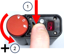
| 11211 - Initiate self-test |
Instruction
|
Published
|
10/01/2024 11:30 PM
|
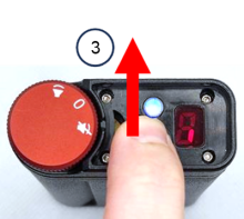
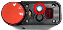
| 11207 - 1 – Hold down display button. 2 – While holding display button, tu... |
Remark
|
Published
|
10/01/2024 11:30 PM
|
| 11208 - TA600 Initiate Self-test Hold Turn to Vibrate mode |
Remark
|
Published
|
10/01/2024 11:31 PM
|
| 11209 - 3 – Release display button after LED flashes blue |
Remark
|
Published
|
10/01/2024 11:32 PM
|
| 11210 - TA600 Initiate Self-test Release After Blue LED |
Remark
|
Published
|
10/01/2024 11:36 PM
|
| 11255 - 11254 - Observe self-test; Remark:11244 |
Procedure Step
|
Published
|
10/02/2024 12:12 AM
|
| 11254 - Observe self-test |
Instruction
|
Published
|
10/01/2024 11:51 PM
|
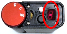
| 11244 - The instrument will go through several routines in rapid succession. L... |
Remark
|
Published
|
10/01/2024 11:51 PM
|
| 11245 - TA600 Observe self-test LED will rapidly flash |
Remark
|
Published
|
10/02/2024 12:03 AM
|
| 11246 - All segments of segmented display will illuminate sequentially. |
Remark
|
Published
|
10/02/2024 12:03 AM
|
| 11247 - TA600 Observe Self-test Display will illuminate sequentially |
Remark
|
Published
|
10/02/2024 12:04 AM
|
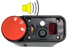
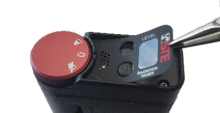
| 11248 - Instrument will beep |
Remark
|
Published
|
10/02/2024 12:05 AM
|
| 11249 - TA600 Observe Self-test, Instrument will beep |
Remark
|
Published
|
10/02/2024 12:06 AM
|
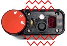
| 11250 - Instrument will vibrate |
Remark
|
Published
|
10/02/2024 12:06 AM
|
| 11251 - TA600 Observe Self-test, Instrument will vibrate |
Remark
|
Published
|
10/02/2024 12:08 AM
|
| 11252 - Middle LED segment will flash and disappear |
Remark
|
Published
|
10/02/2024 12:08 AM
|
| 11253 - TA600 Observe Self-test, middle LED segment will flash and disappear |
Remark
|
Published
|
10/02/2024 12:11 AM
|
| 11256 - 11243 - Verify successful self-test; Remark:11241 |
Procedure Step
|
Published
|
10/02/2024 12:14 AM
|
| 11243 - Verify successful self-test |
Instruction
|
Published
|
10/02/2024 12:12 AM
|
| 11241 - The self-test is successful if actions were observed. If the middle LED segment ... |
Remark
|
Published
|
10/02/2024 12:12 AM
|
| 11242 - TA600 self-test is successful if actions were observed |
Remark
|
Published
|
10/02/2024 12:14 AM
|
| 11272 - 319 - Perform operational test; Remark:11271 |
Procedure Step
|
Published
|
10/02/2024 12:19 AM
|
| 319 - Perform operational test |
Instruction
|
Published
|
06/10/2021 8:31 PM
|
| 11271 - DET-HHD-STE-TA6-RM01, TA600 Operational Test |
Remark
|
Published
|
10/02/2024 12:19 AM
|
| 11270 - 11269 - Complete Assembly; Remark: |
Procedure Step
|
Published
|
10/02/2024 12:21 AM
|
| 11269 - Complete Assembly |
Instruction
|
Published
|
10/02/2024 12:20 AM
|
| 11265 - 313 - Power off instrument; Remark:11093 |
Procedure Step
|
Published
|
10/02/2024 12:23 AM
|
| 11266 - 11073 - Clean top housing; Remark:11264 |
Procedure Step
|
Published
|
10/02/2024 12:24 AM
|
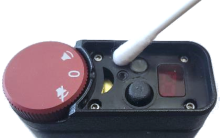
| 11073 - Clean top housing |
Instruction
|
Published
|
10/01/2024 7:12 PM
|
| 11264 - Use cotton swab with alcohol. Carefully clean top of instrument. This will remov... |
Remark
|
Published
|
10/02/2024 12:24 AM
|
| 11273 - TA600 Clean top housing |
Remark
|
Published
|
10/02/2024 12:47 AM
|
| 11268 - 11260 - Apply enclosure label; Remark:11258 |
Procedure Step
|
Published
|
10/02/2024 12:29 AM
|
| 11260 - Apply enclosure label |
Instruction
|
Published
|
10/02/2024 12:27 AM
|
| 11258 - Remove label backing. Align label on top housing. |
Remark
|
Published
|
10/02/2024 12:27 AM
|
| 11259 - TA600 Apply enclosure label |
Remark
|
Published
|
10/02/2024 12:29 AM
|
| 322 - 321 - Document maintenance actions; Remark: |
Procedure Step
|
Published
|
06/17/2021 9:49 AM
|
| 321 - Document maintenance actions |
Instruction
|
Published
|
04/21/2025 11:19 AM
|
| 2869 - 2585 - Document maintenance performed; Remark:2866 |
Procedure Step
|
Published
|
06/18/2021 5:58 PM
|
| 2585 - Document maintenance performed |
Instruction
|
Published
|
07/09/2021 12:15 PM
|
| 2866 - Record observations, times, and results for the maintenance report. |
Remark
|
Published
|
04/21/2025 11:39 AM
|
| 4706 - 4705 - Submit report; Remark:4864 |
Procedure Step
|
Published
|
06/29/2022 9:50 AM
|
| 4705 - Submit report |
Instruction
|
Published
|
06/29/2022 9:50 AM
|
| 4864 - As specified by management or contractual obligations. |
Remark
|
Published
|
07/28/2022 1:36 PM
|
| Corrective Maintenance Procedure |
Document Type
|
Published
|
03/02/2020 3:32 PM
|
| hour |
Duration
|
Published
|
05/26/2022 11:41 AM
|
| As Needed |
Frequency
|
Published
|
04/01/2020 11:36 AM
|
| Display button is difficult to press |
Frequency
|
Published
|
10/02/2024 6:09 AM
|
| Power knob is difficult to turn |
Frequency
|
Published
|
10/02/2024 6:09 AM
|
| Caution |
Annotation Type
|
Published
|
03/02/2020 3:24 PM
|
| Technician 2 |
Skill Level
|
Published
|
04/09/2020 1:17 AM
|
| Coin screwdriver (STE Part# 8125-9-45) |
Tools
|
Published
|
10/02/2024 6:14 AM
|
| Tweezers |
Tools
|
Published
|
08/30/2022 4:28 PM
|
| 0.05-in. hex driver |
Replacement Parts
|
Published
|
10/01/2024 7:27 PM
|
| TA600 Verify Knob Alignment |
Image
|
Published
|
10/01/2024 7:27 PM
|
| TA600 Locate battery cover |
Image
|
Published
|
10/01/2024 11:06 PM
|
| TA600 Use a coin screwdriver, rotate counterclockwise |
Image
|
Published
|
10/01/2024 11:06 PM
|
| TA600 Remove battery cover, rotate counterclockwise |
Image
|
Published
|
10/01/2024 11:06 PM
|
| TA600 Use coin, rotate counterclockwise |
Image
|
Published
|
10/01/2024 11:06 PM
|
| TA600 Remove battery |
Image
|
Published
|
10/01/2024 11:06 PM
|
| TA600 Remove label with tweezers |
Image
|
Published
|
10/01/2024 11:06 PM
|
| TA600 Remove label with sharp blade |
Image
|
Published
|
10/01/2024 11:06 PM
|
| TA600 Remove four screws |
Image
|
Published
|
10/01/2024 11:06 PM
|
| TA600 Retain screws and washers |
Image
|
Published
|
10/01/2024 11:06 PM
|
| TA600 Separate top and bottom enclosures |
Image
|
Published
|
10/01/2024 11:06 PM
|
| TA600 Disconnect rotary switch board |
Image
|
Published
|
10/01/2024 11:06 PM
|
| TA600 Separate circuit boards |
Image
|
Published
|
10/01/2024 11:06 PM
|
| TA600 Disconnect piezo connector |
Image
|
Published
|
10/01/2024 11:06 PM
|
| TA600 Use New Top Housing |
Image
|
Published
|
10/01/2024 11:06 PM
|
| TA600 Insert PCBA into top housing |
Image
|
Published
|
10/01/2024 11:06 PM
|
| TA600 Route wires under rotary switch |
Image
|
Published
|
10/01/2024 11:06 PM
|
| TA600 Insert four enclosure screws and washers |
Image
|
Published
|
10/01/2024 11:06 PM
|
| TA600 Verify screws do not interfere with piezo wires |
Image
|
Published
|
10/01/2024 11:06 PM
|
| TA600 Connect PCBAs line up pins with sockets |
Image
|
Published
|
10/01/2024 11:06 PM
|
| TA600 Connect rotary switch board |
Image
|
Published
|
10/01/2024 11:37 PM
|
| TA600 Place top housing, route wire to avoid screws |
Image
|
Published
|
10/01/2024 11:37 PM
|
| TA600 Evenly tighten screws |
Image
|
Published
|
10/01/2024 11:37 PM
|
| TA600 Tighten screws until gasket compressed |
Image
|
Published
|
10/01/2024 11:37 PM
|
| TA600 Gasket is lightly compressed |
Image
|
Published
|
10/01/2024 11:37 PM
|
| TA600_Verify_enclosure_screws_tightened_correctly_0.png |
Image
|
Published
|
10/02/2024 9:59 AM
|
| TA600 Insert battery |
Image
|
Published
|
10/01/2024 11:37 PM
|
| TA600 Use a coin screwdriver, rotate clockwise |
Image
|
Published
|
10/01/2024 11:37 PM
|
| TA600 Use a slotted screwdriver, or coin, rotate clockwise |
Image
|
Published
|
10/01/2024 11:37 PM
|
| TA600 Initiate Self-test Hold Turn to Vibrate mode |
Image
|
Published
|
10/01/2024 11:37 PM
|
| TA600 Initiate Self-test Release After Blue LED |
Image
|
Published
|
10/01/2024 11:37 PM
|
| TA600 Observe self-test LED will rapidly flash |
Image
|
Published
|
10/02/2024 12:14 AM
|
| TA600 Observe Self-test Display will illuminate sequentially |
Image
|
Published
|
10/02/2024 12:14 AM
|
| TA600 Observe Self-test, Instrument will beep |
Image
|
Published
|
10/02/2024 12:14 AM
|
| TA600 Observe Self-test, Instrument will vibrate |
Image
|
Published
|
10/02/2024 12:14 AM
|
| TA600 Observe Self-test |
Image
|
Published
|
10/02/2024 12:14 AM
|
| TA600 Clean top housing |
Image
|
Published
|
10/02/2024 12:30 AM
|
| TA600 Apply enclosure label |
Image
|
Published
|
10/02/2024 12:30 AM
|