Last Updated: 06/08/2025 1:44 AM
The following table lists all the components that make up the document.
Instruction for safely removing an alarm strobe assembly and correctly installing a new one
Prior to arrival, notify operators concerning expected work, duration, and anticipated alarms and fault indications.
Updated pillar names
8489 - 1401 - Establish Initial Conditions; Remark:
7265 - Warning : Traffic should temporarily be rerouted or halted during this procedure to ens...
Traffic should temporarily be rerouted or halted during this procedure to ensure safety and prevent unscreened vehicles from passing.
1401 - Establish Initial Conditions
Establish Initial Conditions
8490 - 7592 - Inform system operators; Remark:
7592 - Inform system operators
Inform system operators
8221 - 7676 - Brief system operators on expected work, duration, anticipated alarms, and fa...; Remark:
7676 - Brief system operators on expected work, duration, anticipated alarms, and fa...
Brief system operators on expected work, duration, anticipated alarms, and fault indications before starting work
10262 - 7967 - Close lane and set up barriers or establish a safety watch; Remark:7595
7967 - Close lane and set up barriers or establish a safety watch
Close lane and set up barriers or establish a safety watch
7595 - Use orange safety (traffic control) cones or equivalent per site-specific saf...
Use orange safety (traffic control) cones or equivalent per site-specific safety practices.
10264 - 9235 - Open Control pillar RPM door; Remark:
9235 - Open Control pillar RPM door
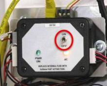
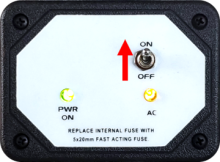
10265 - 9236 - Switch LD-260 to OFF position and verify green “PWR ON” LED is not lit; Remark:10263
9236 - Switch LD-260 to OFF position and verify green “PWR ON” LED is not lit
10263 -
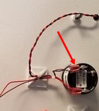
8719 - 8672 - Disconnect Strobe Light Wiring; Remark:
8672 - Disconnect Strobe Light Wiring
Disconnect Strobe Light Wiring
8720 - 8673 - Locate terminal block TB4; Remark:8674
8675 - Note : If repairing a pedestrian monitor, go to Step 2-4
If repairing a pedestrian monitor, go to Step 2-4
8673 - Locate terminal block TB4
Locate terminal block TB4
8674 - For vehicle monitors: Open the upper RPM door
For vehicle monitors: Open the upper RPM door
For train monitors: Open the control cabinet
8721 - 8676 - Disconnect wiring from terminal block TB4; Remark:8677
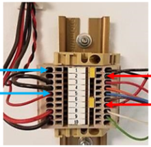
8676 - Disconnect wiring from terminal block TB4
Disconnect wiring from terminal block TB4
8677 - Using a small flathead screwdriver, for the blue neutron strobe, remove wires...
Using a small flathead screwdriver, for the blue neutron strobe, remove wires:
Red wire - Pin 5
Black wire - Pin 1
Using a small flathead screwdriver, for the red gamma strobe, remove wires:
Red wire - Pin 7
Black wire - Pin 2
8722 - 8678 - Release wiring harness from fasteners; Remark:8679
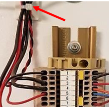
8678 - Release wiring harness from fasteners
Release wiring harness from fasteners
8723 - 8680 - Identify strobe light wiring (for pedestrian monitor); Remark:8681
8680 - Identify strobe light wiring (for pedestrian monitor)
Identify strobe light wiring (for pedestrian monitor)
8681 - Blue neutron strobe: Positive terminal (+): Two (2...
Blue neutron strobe:
Positive terminal (+): Two (2) red wires
Negative terminal (P): One (1) blue wire and one (1) black wire
Red gamma strobe
Positive terminal: Two (2) red wires
Negative terminal (S): One (1) brown wire and one (1) black wire
8724 - 8678 - Release wiring harness from fasteners; Remark:8682
8678 - Release wiring harness from fasteners
Release wiring harness from fasteners
8682 - Use cutter pliers to remove any fasteners associated wth strobe light wiring....
Use cutter pliers to remove any fasteners associated wth strobe light wiring.
8725 - 8683 - Disconnect wires from strobe light wiring; Remark:8684
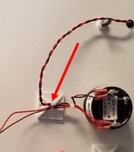
8683 - Disconnect wires from strobe light wiring
Disconnect wires from strobe light wiring
8684 - Remove forked connectors from Sonalert using a small Phillips screwdriver. Us...
Remove forked connectors from Sonalert using a small Phillips screwdriver. Use cutter pliers to remove forked connectors from strobe wires.
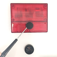
8726 - 8685 - Uninstall Red and Blue Strobe Assemblies; Remark:
8685 - Uninstall Red and Blue Strobe Assemblies
Uninstall Red and Blue Strobe Assemblies
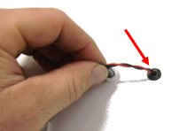
8727 - 8686 - Remove circular black cover from strobe light; Remark:8687
8686 - Remove circular black cover from strobe light
Remove circular black cover from strobe light
8687 - Use a small flathead screwdriver to pry the circular black cover off.
Use a small flathead screwdriver to pry the circular black cover off.
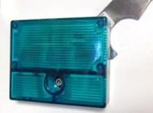
8728 - 8688 - Remove strobe light assembly; Remark:8689
8688 - Remove strobe light assembly
Remove strobe light assembly
8689 - Use a 3/16" Allen wrench to remove strobe light assembly.
Use a 3/16" Allen wrench to remove strobe light assembly.

8729 - 8690 - Pry strobe assembly from RPM door; Remark:8691
8690 - Pry strobe assembly from RPM door
Pry strobe assembly from RPM door
8691 - Use a putty knife to pry strobe assembly off RPM door.
Use a putty knife to pry strobe assembly off RPM door.
8730 - 8692 - Pull hardware assembly with wires to remove; Remark:
8692 - Pull hardware assembly with wires to remove
Pull hardware assembly with wires to remove
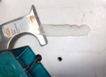
8731 - 8693 - Remove residue off RPM door; Remark:8694
8693 - Remove residue off RPM door
Remove residue off RPM door
8694 - Use a putty knife to remove silicone or residue off RPM door.
Use a putty knife to remove silicone or residue off RPM door.
3397 - 3395 - Label faulty component; Remark:3396
3395 - Label faulty component
Label faulty component
3396 - Use tag or tape. Include date of removal, description of failure symptoms, co...
Use tag or tape. Include date of removal, description of failure symptoms, country, site, and lane number. Dispose per Nuclear Smuggling Detection and Deterrence (NSDD) guidance or contractual requirements.
8732 - 8695 - Install and Seal New Red and Blue Strobe Assembly; Remark:
8695 - Install and Seal New Red and Blue Strobe Assembly
Install and Seal New Red and Blue Strobe Assembly
8733 - 8696 - Route strobe light assembly wires; Remark:8697
8696 - Route strobe light assembly wires
Route strobe light assembly wires
8697 - Insert new strobe light assembly wires through grommet located in RPM door.
Insert new strobe light assembly wires through grommet located in RPM door.
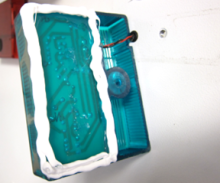
8734 - 8699 - Apply silicone to strobe light assembly; Remark:8700
8701 - Warning : Use protective gloves when handling silicone.
Use protective gloves when handling silicone.
8699 - Apply silicone to strobe light assembly
Apply silicone to strobe light assembly
8735 - 8702 - Install new strobe light assembly to front of door; Remark:8703
8702 - Install new strobe light assembly to front of door
Install new strobe light assembly to front of door
8703 - Align strobe assembly hole to the hole in the front of the RPM door. Then, fi...
Align strobe assembly hole to the hole in the front of the RPM door. Then, firmly press on edges to ensure silicone adheres to the door surface.
8736 - 8704 - Tighten strobe light assembly; Remark:8705
8706 - Caution : Do not overtighten hardware
Do not overtighten hardware
8704 - Tighten strobe light assembly
Tighten strobe light assembly
8705 - Use a 3/16" Allen wrench to tighten clockwise until secure.
Use a 3/16" Allen wrench to tighten clockwise until secure.
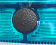
8738 - 8707 - Insert circular black cover on strobe light assembly; Remark:8708
8707 - Insert circular black cover on strobe light assembly
Insert circular black cover on strobe light assembly
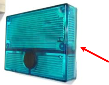
8737 - 8709 - Remove excess silicone from around strobe light assembly edges; Remark:8710
8701 - Warning : Use protective gloves when handling silicone.
Use protective gloves when handling silicone.
8709 - Remove excess silicone from around strobe light assembly edges
Remove excess silicone from around strobe light assembly edges
8739 - 8711 - Reconnect Strobe Light Wiring; Remark:
8711 - Reconnect Strobe Light Wiring
Reconnect Strobe Light Wiring
8740 - 8713 - Reconnect wiring from terminal TB4; Remark:8677
8712 - Note : If repairing a pedestrian monitor, go to Step 5-4
If repairing a pedestrian monitor, go to Step 5-4
7263 - Caution : Correct placement of connectors and wiring is critical to proper operation.
Correct placement of connectors and wiring is critical to proper operation.
8713 - Reconnect wiring from terminal TB4
Reconnect wiring from terminal TB4
8677 - Using a small flathead screwdriver, for the blue neutron strobe, remove wires...
Using a small flathead screwdriver, for the blue neutron strobe, remove wires:
Red wire - Pin 5
Black wire - Pin 1
Using a small flathead screwdriver, for the red gamma strobe, remove wires:
Red wire - Pin 7
Black wire - Pin 2
8741 - 8714 - Add wire fasteners where removed; Remark:
8714 - Add wire fasteners where removed
Add wire fasteners where removed
8742 - 8680 - Identify strobe light wiring (for pedestrian monitor); Remark:8681
8680 - Identify strobe light wiring (for pedestrian monitor)
Identify strobe light wiring (for pedestrian monitor)
8681 - Blue neutron strobe: Positive terminal (+): Two (2...
Blue neutron strobe:
Positive terminal (+): Two (2) red wires
Negative terminal (P): One (1) blue wire and one (1) black wire
Red gamma strobe
Positive terminal: Two (2) red wires
Negative terminal (S): One (1) brown wire and one (1) black wire
8743 - 8715 - Crimp forked connectors to end of strobe light wires; Remark:8716
8715 - Crimp forked connectors to end of strobe light wires
Crimp forked connectors to end of strobe light wires
8716 - Remove ¼ inch (6mm) of insulation from the strobe light assembly wire end us...
Remove ¼ inch (6mm) of insulation from the strobe light assembly wire end using wire stripper (if necessary). Insert end of wire into terminal end and crimp using a crimping tool.
8744 - 8717 - Connect strobe light assembly wire to Sonalert; Remark:8718
7263 - Caution : Correct placement of connectors and wiring is critical to proper operation.
Correct placement of connectors and wiring is critical to proper operation.
8717 - Connect strobe light assembly wire to Sonalert
Connect strobe light assembly wire to Sonalert
8718 - Using a small Phillips screwdriver, terminate the forked connectors to the co...
Using a small Phillips screwdriver, terminate the forked connectors to the correct locations on the Sonalert.
7279 - 7249 - Return equipment to normal operating condition; Remark:
7249 - Return equipment to normal operating condition
Return equipment to normal operating condition
8503 - 7250 - Power on RPM; Remark:7251
7250 - Power on RPM
Power on RPM
7251 - Move LD-260 switch to ON position. The LED PWR ON
Move LD-260 switch to ON position. The LED PWR ON will illuminate.
8506 - 7254 - Confirm network connection; Remark:7255
7254 - Confirm network connection
Confirm network connection
7255 - Contact operators to confirm communications have been reestablished between RPM ...
8258 - 319 - Perform operational test; Remark:8219
319 - Perform operational test
Perform operational test
8219 - DET-RPM-RAP-RM03, Operational Testing procedure.
DET-RPM-RAP-RM03, Operational Testing procedure.
8507 - 7256 - Close and lock all RPM doors; Remark:
7256 - Close and lock all RPM doors
Close and lock all RPM doors
7842 - 7820 - Inform system operators upon completion of maintenance action; Remark:
7820 - Inform system operators upon completion of maintenance action
Inform system operators upon completion of maintenance action
322 - 321 - Document maintenance actions; Remark:
321 - Document maintenance actions
Document maintenance actions
2869 - 2585 - Document maintenance performed; Remark:2866
2585 - Document maintenance performed
Document maintenance performed
2866 - Record observations, times, and results for the maintenance report.
Record observations, times, and results for the maintenance report.
4706 - 4705 - Submit report; Remark:4864
4705 - Submit report
Submit report
4864 - As specified by management or contractual obligations.
As specified by management or contractual obligations.