Last Updated: 04/24/2025 1:41 AM
The following table lists all the components that make up the document.
This procedure provides comprehensive instruction on the disassembly and reassembly of the RadSeeker. This includes the removal of detectors and all printed circuit boards (PCBs) except for the display PCB. This procedure is referenced in other documents for removal of the gamma detector and multi-channel analyzer (MCA). It is not usually necessary to complete the entire procedure; only steps needed to access specific components. If a torque screwdriver tool is not available, take care not to overtighten screws.
Prior to arrival, notify operators concerning expected work and duration.
5017 - 5016 - Disassemble Enclosure; Remark:
5016 - Disassemble Enclosure
Disassemble Enclosure
5271 - 5270 - Remove battery; Remark:5269
5270 - Remove battery
Remove battery
5269 - Unclasp battery door. Open battery door. Use tab to pull battery. Close and r...
Unclasp battery door. Open battery door. Use tab to pull battery. Close and reclasp battery door after removal.

5278 - 5277 - Orient RadSeeker; Remark:5276
5277 - Orient RadSeeker
Orient RadSeeker
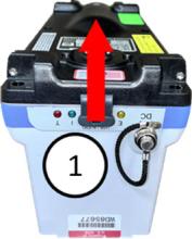
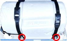
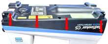
5276 - Rotate RadSeeker to expose underside and bumpers.
Rotate RadSeeker to expose underside and bumpers.
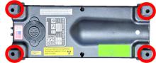
5281 - 5280 - Loosen eight (8) bumper screws; Remark:5279
5280 - Loosen eight (8) bumper screws
Loosen eight (8) bumper screws
5279 - Use small Phillips (PH1) screwdriver. Each bumper contains two (2) screws for...
Use small Phillips (PH1) screwdriver. Each bumper contains two (2) screws for a total of eight (8) screws. Retain screws within bumpers.
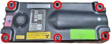
5284 - 5283 - Remove six (6) enclosure screws; Remark:5282
5288 - Note : Enclosure screws might be Phillips (PH2) or T4 Torx.
Enclosure screws might be Phillips (PH2) or T4 Torx.
5283 - Remove six (6) enclosure screws
Remove six (6) enclosure screws
5282 - Use medium Phillips (PH2) screwdriver (or T4 Torx screwdriver if applicable)....
Use medium Phillips (PH2) screwdriver (or T4 Torx screwdriver if applicable). Retain screws.
5287 - 5286 - Remove bottom cover; Remark:5285
5286 - Remove bottom cover
Remove bottom cover
5285 - Lift vertically. Rotate cover. Set cover down on same side as cable connectio...
Lift vertically. Rotate cover. Set cover down on same side as cable connection.

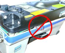
5292 - 5290 - Disconnect beeper; Remark:5289
1345 - Note : It is good practice to ensure all cables and connectors are labeled prior to ...
It is good practice to ensure all cables and connectors are labeled prior to disconnection.
5290 - Disconnect beeper
Disconnect beeper
5289 - Use needle nose pliers. Pull connector directly away from circuit board. ...
Use needle nose pliers. Pull connector directly away from circuit board.

5015 - 5014 - Uninstall Processor PCB; Remark:
5293 - Caution : An electrostatic discharge wrist-strap should be worn to prevent damage to el...
An electrostatic discharge wrist-strap should be worn to prevent damage to electronic components.
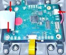
5014 - Uninstall Processor PCB
Uninstall Processor PCB
5295 - 5294 - Disconnect Wi-Fi antenna; Remark:5289
1345 - Note : It is good practice to ensure all cables and connectors are labeled prior to ...
It is good practice to ensure all cables and connectors are labeled prior to disconnection.
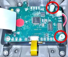
5294 - Disconnect Wi-Fi antenna
Disconnect Wi-Fi antenna
5289 - Use needle nose pliers. Pull connector directly away from circuit board. ...
Use needle nose pliers. Pull connector directly away from circuit board.

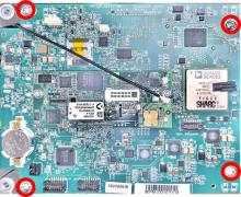
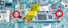
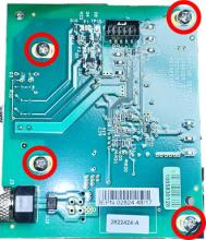
5298 - 5297 - Remove four (4) processor PCB screws; Remark:5296
5297 - Remove four (4) processor PCB screws
Remove four (4) processor PCB screws
5296 - Use small Phillips (PH1) screwdriver. Retain screws.
Use small Phillips (PH1) screwdriver. Retain screws.
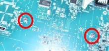
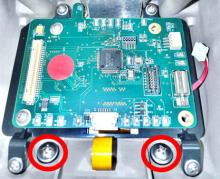
5301 - 5300 - Remove two (2) USB dust cover screws; Remark:5299
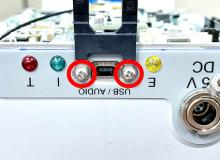
5300 - Remove two (2) USB dust cover screws
Remove two (2) USB dust cover screws
5299 - Use very small Phillips (PH0) screwdriver. Retain screws, washers and dust co...
Use very small Phillips (PH0) screwdriver. Retain screws, washers and dust cover.
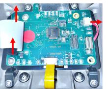
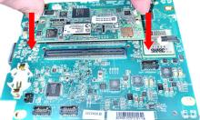
5304 - 5302 - Lift processor PCB; Remark:5331
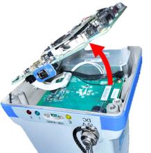
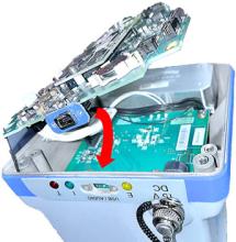
5303 - Caution : Wiring and cables are still connected to the underside of the component. ...
Wiring and cables are still connected to the underside of the component.
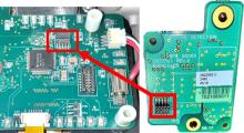
5302 - Lift processor PCB
Lift processor PCB
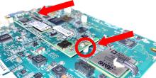
5307 - 5306 - Disconnect five (5) processor PCB cables; Remark:5305
1345 - Note : It is good practice to ensure all cables and connectors are labeled prior to ...
It is good practice to ensure all cables and connectors are labeled prior to disconnection.
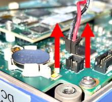
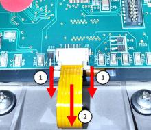
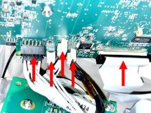
5306 - Disconnect five (5) processor PCB cables
Disconnect five (5) processor PCB cables
5305 - Push in the tabs of the two (2) connectors with this feature.
Push in the tabs of the two (2) connectors with this feature.
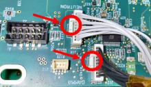
5332 - Pull connectors directly away from circuit board. Set aside processor PCB.
Pull connectors directly away from circuit board. Set aside processor PCB.
5005 - 5004 - Uninstall SOM; Remark:
5311 - Note : The SOM [System On Module] Assembly can remain attached to the processor PCB ...
The SOM [System On Module] Assembly can remain attached to the processor PCB if it is not being replaced.
5004 - Uninstall SOM
Uninstall SOM
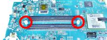
5310 - 5309 - Remove two (2) screws; Remark:5308
5309 - Remove two (2) screws
Remove two (2) screws
5308 - Use 5/64" hex key in conjunction with 3/16" nut driver on underside of PCB. R...
Use 5/64" hex key in conjunction with 3/16" nut driver on underside of PCB. Retain screws, nuts and washers.
5314 - 5313 - Remove two (2) spacers; Remark:5312
5003 - 5002 - Uninstall Gamma Detector Assembly; Remark:
5002 - Uninstall Gamma Detector Assembly
Uninstall Gamma Detector Assembly
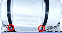
5317 - 5316 - Remove four (4) gamma detector screws; Remark:5315
5316 - Remove four (4) gamma detector screws
Remove four (4) gamma detector screws
5315 - Use medium Phillips (PH2) screwdriver. Retain screws.
Use medium Phillips (PH2) screwdriver. Retain screws.
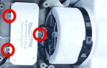
5319 - 5318 - Remove three (3) MCA screws; Remark:5296
5318 - Remove three (3) MCA screws
Remove three (3) MCA screws
5296 - Use small Phillips (PH1) screwdriver. Retain screws.
Use small Phillips (PH1) screwdriver. Retain screws.
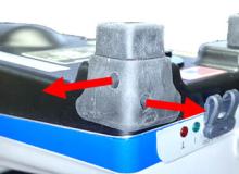
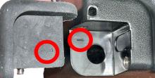
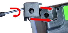
5340 - 5339 - Remove mounting bracket tab; Remark:5338
5339 - Remove mounting bracket tab
Remove mounting bracket tab
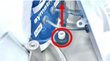
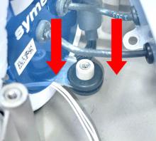
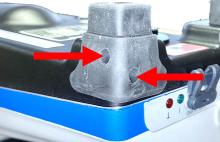
5338 - Carefully pry grommet off of mounting post.
Carefully pry grommet off of mounting post.
5341 - 5337 - Remove gamma detector assembly; Remark:5336
5337 - Remove gamma detector assembly
Remove gamma detector assembly
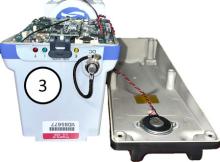
5336 - Simultaneously lift the MCA and gamma detector and set aside.
Simultaneously lift the MCA and gamma detector and set aside.
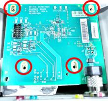
5001 - 5000 - Uninstall Charger PCB; Remark:
5000 - Uninstall Charger PCB
Uninstall Charger PCB
5366 - 5365 - Disconnect charger PCB cable; Remark:5364
1345 - Note : It is good practice to ensure all cables and connectors are labeled prior to ...
It is good practice to ensure all cables and connectors are labeled prior to disconnection.
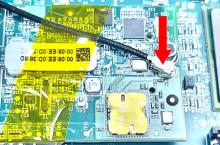
5365 - Disconnect charger PCB cable
Disconnect charger PCB cable
5364 - Pull connector directly away from circuit board.
Pull connector directly away from circuit board.
5367 - 5363 - Remove four (4) screws; Remark:5362
5363 - Remove four (4) screws
Remove four (4) screws
5362 - Use small Phillips (PH1) screwdriver. Retain screws and washers.
Use small Phillips (PH1) screwdriver. Retain screws and washers.
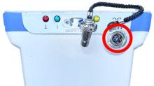
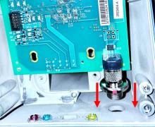
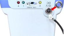
5368 - 5361 - Remove DC cover; Remark:5360
5361 - Remove DC cover
Remove DC cover
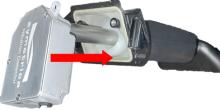
5360 - Use spanner screwdriver with spanner bit (Series 80, Shell size 7). Needle no...
Use spanner screwdriver with spanner bit (Series 80, Shell size 7). Needle nose pliers can be used if spanner is not available.
5514 - IO RadSeeker DC Cover Spanner Screwdriver
IO RadSeeker DC Cover Spanner Screwdriver

4999 - 4998 - Uninstall GPS PCB; Remark:
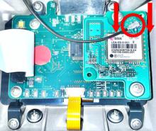
4998 - Uninstall GPS PCB
Uninstall GPS PCB
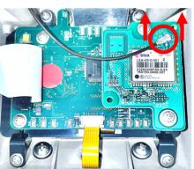
5380 - 5379 - Disconnect GPS antenna; Remark:5289
1345 - Note : It is good practice to ensure all cables and connectors are labeled prior to ...
It is good practice to ensure all cables and connectors are labeled prior to disconnection.
5379 - Disconnect GPS antenna
Disconnect GPS antenna
5289 - Use needle nose pliers. Pull connector directly away from circuit board. ...
Use needle nose pliers. Pull connector directly away from circuit board.
5378 - IO RadSeeker GPS Remove Connector Away
IO RadSeeker GPS Remove Connector Away
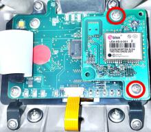
5381 - 5309 - Remove two (2) screws; Remark:5296
5309 - Remove two (2) screws
Remove two (2) screws
5296 - Use small Phillips (PH1) screwdriver. Retain screws.
Use small Phillips (PH1) screwdriver. Retain screws.
5377 - IO RadSeeker GPS Two Mounting Screws
IO RadSeeker GPS Two Mounting Screws
5382 - 5376 - Remove GPS PCB; Remark:5375
5376 - Remove GPS PCB
Remove GPS PCB
5375 - IO RadSeeker GPS PCB Remove
IO RadSeeker GPS PCB Remove

5383 - 5313 - Remove two (2) spacers; Remark:5312
4997 - 4996 - Uninstall Neutron Detector; Remark:
4996 - Uninstall Neutron Detector
Uninstall Neutron Detector
5417 - 5416 - Disconnect display PCB connectors; Remark:5415
1345 - Note : It is good practice to ensure all cables and connectors are labeled prior to ...
It is good practice to ensure all cables and connectors are labeled prior to disconnection.
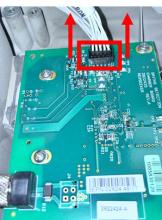
5416 - Disconnect display PCB connectors
Disconnect display PCB connectors
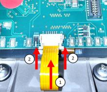
5418 - 5414 - Disconnect keypad cable; Remark:5413
5414 - Disconnect keypad cable
Disconnect keypad cable
5413 - Pull out cable tabs, then remove cable.
Pull out cable tabs, then remove cable.
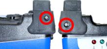
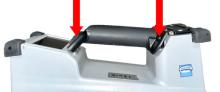
5419 - 5412 - Remove two (2) internal handle screws; Remark:5411
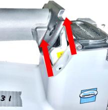
5412 - Remove two (2) internal handle screws
Remove two (2) internal handle screws
5411 - Use small Phillips (PH1) screwdriver. Retain screws, washers and O-rings....
Use small Phillips (PH1) screwdriver. Retain screws, washers and O-rings.
5420 - 5410 - Remove two (2) external handle screws; Remark:5296
5410 - Remove two (2) external handle screws
Remove two (2) external handle screws
5296 - Use small Phillips (PH1) screwdriver. Retain screws.
Use small Phillips (PH1) screwdriver. Retain screws.

5421 - 5407 - Remove RadSeeker handle/neutron detector; Remark:5406
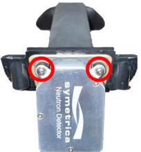
5408 - Caution : The neutron detector electronics are connected to the handle. Remove neutron ...
The neutron detector electronics are connected to the handle. Remove neutron detector at an angle to avoid damage.
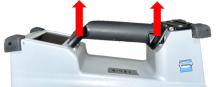
5407 - Remove RadSeeker handle/neutron detector
Remove RadSeeker handle/neutron detector
5406 - Pull directly away from enclosure to loosen handle.
Pull directly away from enclosure to loosen handle.
5422 - 5405 - Remove two (2) mounting screws; Remark:5404
5405 - Remove two (2) mounting screws
Remove two (2) mounting screws
5404 - Use small Phillips (PH1) screwdriver.
Use small Phillips (PH1) screwdriver.
5423 - 5402 - Remove neutron detector from handle; Remark:5401
5403 - Caution : Do not remove moderator unless it will be replaced.
Do not remove moderator unless it will be replaced.
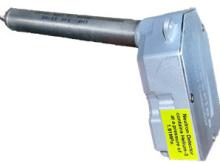
5402 - Remove neutron detector from handle
Remove neutron detector from handle
5401 - Inspect neutron tube for damage.
Inspect neutron tube for damage.
4995 - 4994 - Reinstall Neutron Detector; Remark:
4994 - Reinstall Neutron Detector
Reinstall Neutron Detector
5456 - 5455 - Insert neutron tube into handle; Remark:5454
5455 - Insert neutron tube into handle
Insert neutron tube into handle
5454 - Insert directly downward into moderator material.
Insert directly downward into moderator material.
5457 - 5453 - Replace two (2) mounting screws; Remark:5404
5453 - Replace two (2) mounting screws
Replace two (2) mounting screws
5404 - Use small Phillips (PH1) screwdriver.
Use small Phillips (PH1) screwdriver.
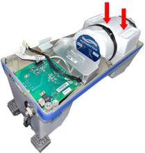
5458 - 5452 - Insert handle; Remark:5450
5452 - Insert handle
Insert handle
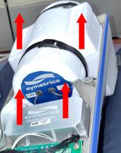
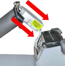
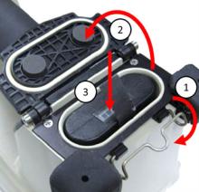
5450 - Place module into chassis at an angle, then press directly down on the handle...
Place module into chassis at an angle, then press directly down on the handle with even pressure.
5451 - IO RadSeeker Handle Install / Press Down

5459 - 5449 - Replace two (2) external handle screws; Remark:5404
5449 - Replace two (2) external handle screws
Replace two (2) external handle screws
5404 - Use small Phillips (PH1) screwdriver.
Use small Phillips (PH1) screwdriver.
5460 - 5447 - Replace two (2) internal handle screws; Remark:5446
5447 - Replace two (2) internal handle screws
Replace two (2) internal handle screws
5446 - Use small Phillips (PH1) screwdriver. Seat screws and washers over O-rings.
Use small Phillips (PH1) screwdriver. Seat screws and washers over O-rings.
5461 - 5445 - Reconnect display PCB connectors; Remark:5444
5445 - Reconnect display PCB connectors
Reconnect display PCB connectors
4993 - 4992 - Reinstall GPS Module; Remark:
4992 - Reinstall GPS Module
Reinstall GPS Module
5499 - 5498 - Place GPS PCB spacers; Remark:5497
5498 - Place GPS PCB spacers
Place GPS PCB spacers
5500 - 5496 - Reinsert GPS Module; Remark:5495
5496 - Reinsert GPS Module
Reinsert GPS Module
5495 - Verify pins are aligned.
Verify pins are aligned.

5501 - 5494 - Replace two (2) GPS module mounting screws.; Remark:5404
5494 - Replace two (2) GPS module mounting screws.
Replace two (2) GPS module mounting screws.
5404 - Use small Phillips (PH1) screwdriver.
Use small Phillips (PH1) screwdriver.
5502 - 5492 - Reconnect GPS antenna; Remark:5491
5492 - Reconnect GPS antenna
Reconnect GPS antenna
5491 - Press connector firmly onto GPS module.
Press connector firmly onto GPS module.
4991 - 4990 - Reinstall Charger PCB; Remark:
4990 - Reinstall Charger PCB
Reinstall Charger PCB
5511 - 5509 - Insert DC connector into chassis; Remark:5508
5510 - Caution : Do not damage DC [direct current] connector.
Do not damage DC [direct current] connector.
5509 - Insert DC connector into chassis
Insert DC connector into chassis
5512 - 5506 - Replace four (4) charger PCB mounting screws; Remark:5404
569 - Caution : Do not overtighten screws.
Do not overtighten screws.
5507 - Standard : Torque charger PCB screws to 4 in-lbs.
Torque charger PCB screws to 4 in-lbs.
5506 - Replace four (4) charger PCB mounting screws
Replace four (4) charger PCB mounting screws
5404 - Use small Phillips (PH1) screwdriver.
Use small Phillips (PH1) screwdriver.
5513 - 5503 - Replace DC cover; Remark:5360
5504 - Standard : Torque DC locking nut to 10 in-lbs
Torque DC locking nut to 10 in-lbs
5503 - Replace DC cover
Replace DC cover
5360 - Use spanner screwdriver with spanner bit (Series 80, Shell size 7). Needle no...
Use spanner screwdriver with spanner bit (Series 80, Shell size 7). Needle nose pliers can be used if spanner is not available.
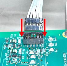
5518 - 5516 - Reinsert charger PCB cable; Remark:5515
5516 - Reinsert charger PCB cable
Reinsert charger PCB cable
5515 - Verify that the tab is oriented correctly and locks in place.
Verify that the tab is oriented correctly and locks in place.
5013 - 5012 - Reinstall Gamma Detector; Remark:
5012 - Reinstall Gamma Detector
Reinstall Gamma Detector
5526 - 5525 - Reinsert gamma detector assembly; Remark:5524
5525 - Reinsert gamma detector assembly
Reinsert gamma detector assembly
5527 - 5481 - Reseat mounting tab; Remark:5480
5482 - Caution : Direct pressure to the metal mounting tab will cause damage. Push down evenly...
Direct pressure to the metal mounting tab will cause damage. Push down evenly ONLY on the rubber grommet.
5481 - Reseat mounting tab
Reseat mounting tab
5480 - Secure grommet over mounting post using even pressure on both sides of the mo...
Secure grommet over mounting post using even pressure on both sides of the mounting grommet.
5528 - 5523 - Replace four (4) gamma detector mounting screws; Remark:5521
569 - Caution : Do not overtighten screws.
Do not overtighten screws.
5467 - Standard : Torque gamma detector screws to 7 in-lbs.
Torque gamma detector screws to 7 in-lbs.
5523 - Replace four (4) gamma detector mounting screws
Replace four (4) gamma detector mounting screws
5521 - Use medium Phillips (PH2) screwdriver.
Use medium Phillips (PH2) screwdriver.
5529 - 5520 - Replace three (3) MCA mounting screws; Remark:5474
569 - Caution : Do not overtighten screws.
Do not overtighten screws.
5490 - Standard : Torque MCA screws to 4 in-lbs.
Torque MCA screws to 4 in-lbs.
5520 - Replace three (3) MCA mounting screws
Replace three (3) MCA mounting screws
5474 - Use small Phillips (PH1) screwdriver.
Use small Phillips (PH1) screwdriver.
5011 - 5010 - Reinstall SOM Assembly; Remark:
5010 - Reinstall SOM Assembly
Reinstall SOM Assembly
5540 - 5539 - Reseat SOM Assembly; Remark:5538
5539 - Reseat SOM Assembly
Reseat SOM Assembly
5538 - Align SOM assembly over processor PCB sockets and connect the components usin...
Align SOM assembly over processor PCB sockets and connect the components using even downward pressure.
5541 - 5537 - Replace two (2) spacers; Remark:5536
5537 - Replace two (2) spacers
Replace two (2) spacers
5536 - Use tweezers to position spacers under SOM module.
Use tweezers to position spacers under SOM module.
5542 - 5453 - Replace two (2) mounting screws; Remark:5534
5453 - Replace two (2) mounting screws
Replace two (2) mounting screws
5534 - Insert screws through SOM assembly and spacers. On the underside of the proce...
Insert screws through SOM assembly and spacers. On the underside of the processor PCB, install flat washer first, then lock washer, and hex nut last.
5009 - 5008 - Reinstall Processor PCB; Remark:
5008 - Reinstall Processor PCB
Reinstall Processor PCB
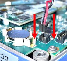
5554 - 5552 - Reconnect five (5) cables to underside of processor PCB; Remark:5551
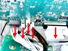
5553 - Caution : Correct placement of connectors and wiring is critical to proper operation.
Correct placement of connectors and wiring is critical to proper operation.
5552 - Reconnect five (5) cables to underside of processor PCB
Reconnect five (5) cables to underside of processor PCB
5555 - 5550 - Insert processor PCB; Remark:5549
5550 - Insert processor PCB
Insert processor PCB
5549 - Fit USB interface into chassis cutout, then lower in processor PCB.
Fit USB interface into chassis cutout, then lower in processor PCB.
5556 - 5547 - Replace two (2) USB dust cover screws; Remark:5545
569 - Caution : Do not overtighten screws.
Do not overtighten screws.
5548 - Standard : Torque USB dust cover screws to 1.6 in-lbs
Torque USB dust cover screws to 1.6 in-lbs
5547 - Replace two (2) USB dust cover screws
Replace two (2) USB dust cover screws
5545 - Use very small Phillips (PH0) screwdriver.
Use very small Phillips (PH0) screwdriver.
5557 - 5544 - Reconnect Wi-Fi cable; Remark:5543
5544 - Reconnect Wi-Fi cable
Reconnect Wi-Fi cable
5543 - Push connector directly toward circuit board.
Push connector directly toward circuit board.
5007 - 5006 - Reassemble Enclosure; Remark:
5006 - Reassemble Enclosure
Reassemble Enclosure
5565 - 5564 - Reconnect beeper cable; Remark:5562
5564 - Reconnect beeper cable
Reconnect beeper cable
5562 - Connector should click securely into place.
Connector should click securely into place.
5566 - 5560 - Replace bottom cover; Remark:5558
5561 - Caution : Verify the silicone tube O-ring does not become pinched or d...
Verify the silicone tube O-ring does not become pinched or damaged when joining enclosures.
5895 - Caution : Verify all wiring is inside the instrument while replacing cover.
Verify all wiring is inside the instrument while replacing cover.
5560 - Replace bottom cover
Replace bottom cover
5558 - Avoid damage to the internal O-ring.
Avoid damage to the internal O-ring.

5559 - Enclosures should fit snugly together.
Enclosures should fit snugly together.
5571 - 5569 - Replace six (6) enclosure screws; Remark:5567
569 - Caution : Do not overtighten screws.
Do not overtighten screws.
5570 - Standard : Torque screws to 7 in-lbs.
Torque screws to 7 in-lbs.
5569 - Replace six (6) enclosure screws
Replace six (6) enclosure screws
5567 - If available, use torque screwdriver set to 7 in-lbs. with medium Phillips (P...
If available, use torque screwdriver set to 7 in-lbs. with medium Phillips (PH2) screwdriver bit.
5574 - 5573 - Verify bumpers are positioned correctly.; Remark:5572
5573 - Verify bumpers are positioned correctly.
Verify bumpers are positioned correctly.
5572 - Each foot and matching bumper should have identifying marks.
Each foot and matching bumper should have identifying marks.
5577 - 5576 - Tighten eight (8) bumper screws; Remark:5575
5576 - Tighten eight (8) bumper screws
Tighten eight (8) bumper screws
5575 - Use small Phillips (PH1) screwdriver. Each bumper contains two (2) screws for...
Use small Phillips (PH1) screwdriver. Each bumper contains two (2) screws for a total of eight (8) screws. Verify screws are secure.
5580 - 10484 - Insert battery pack; Remark:5578
10484 - Insert battery pack
Insert battery pack
5578 - Unclasp battery latch. Open battery latch. Reinsert battery.
Unclasp battery latch. Open battery latch. Reinsert battery.

322 - 321 - Document maintenance actions; Remark:
321 - Document maintenance actions
Document maintenance actions
2869 - 2585 - Document maintenance performed; Remark:2866
2585 - Document maintenance performed
Document maintenance performed
2866 - Record observations, times, and results for the maintenance report.
Record observations, times, and results for the maintenance report.
4706 - 4705 - Submit report; Remark:4864
4705 - Submit report
Submit report
4864 - As specified by management or contractual obligations.
As specified by management or contractual obligations.