Last Updated: 06/10/2025 1:36 AM
The following table lists all the components that make up the document.
Replace PRCB-472 (main circuit board) in PRM-470.
Prior to arrival, notify operators concerning expected work and duration.
247 - 257 - Prepare instrument; Remark:
257 - Prepare instrument
Prepare instrument
607 - 205 - Disconnect charger; Remark:
205 - Disconnect charger
Disconnect charger
260 - 313 - Power off instrument; Remark:
313 - Power off instrument
Power off instrument
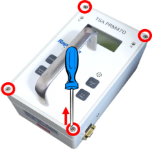
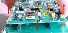
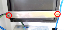
275 - 65 - Loosen four (4) cover screws; Remark:264
65 - Loosen four (4) cover screws
Loosen four (4) cover screws
264 - Use a medium Phillips (PH2) screwdriver. Screws do not need to be completely ...
Use a medium Phillips (PH2) screwdriver. Screws do not need to be completely removed.
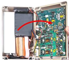
263 - 262 - Remove instrument cover; Remark:413
2771 - Note : There are high-voltage detector circuit boards inside the instrument; however...
There are high-voltage detector circuit boards inside the instrument; however, they carry an extremely small current that does not pose a health risk.
262 - Remove instrument cover
Remove instrument cover
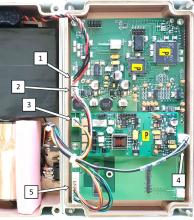
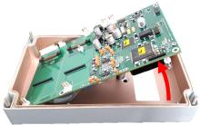
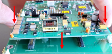
276 - 266 - Locate battery connection; Remark:265
3033 - Note : PRM-470 CGN models have an additional board and connectors not shown in remar...
PRM-470 CGN models have an additional board and connectors not shown in remark images.
266 - Locate battery connection
Locate battery connection
265 - Battery connection is labeled 1.
Battery connection is labeled 1.
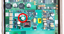
271 - 270 - Disconnect battery; Remark:414
1345 - Note : It is good practice to ensure all cables and connectors are labeled prior to ...
It is good practice to ensure all cables and connectors are labeled prior to disconnection.
270 - Disconnect battery
Disconnect battery

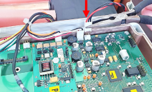
443 - 442 - Disconnect remaining connectors; Remark:
442 - Disconnect remaining connectors
Disconnect remaining connectors
3399 - 3398 - Uninstall GHA-472 board; Remark:
3398 - Uninstall GHA-472 board
Uninstall GHA-472 board
478 - 476 - Remove mounting nut; Remark:477
476 - Remove mounting nut
Remove mounting nut
477 - PRM-470 - Removing GHA-472 mounting nut
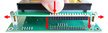
481 - 479 - Remove GHA-472 board; Remark:480
479 - Remove GHA-472 board
Remove GHA-472 board
480 - Gently pry up the GHA-472 board from the PRCB-472 board.
Gently pry up the GHA-472 board from the PRCB-472 board.
618 - 615 - Uninstall PRCB-472 board; Remark:
615 - Uninstall PRCB-472 board
Uninstall PRCB-472 board
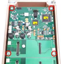
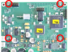
886 - 445 - Remove four (4) mounting screws; Remark:885
445 - Remove four (4) mounting screws
Remove four (4) mounting screws
885 - Use a small Phillips (PH1) screwdriver. Retain screws.
Use a small Phillips (PH1) screwdriver. Retain screws.
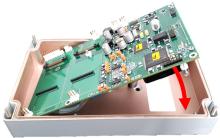
767 - 449 - Raise edge of PRCB-472 board to access underside; Remark:766
447 - Caution : Do not damage ribbon cable attached to the underside of PRCB-472.
Do not damage ribbon cable attached to the underside of PRCB-472.
449 - Raise edge of PRCB-472 board to access underside
Raise edge of PRCB-472 board to access underside
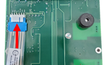
453 - 452 - Disconnect overlay button connector; Remark:451
452 - Disconnect overlay button connector
Disconnect overlay button connector
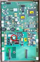
3397 - 3395 - Label faulty component; Remark:3396
3395 - Label faulty component
Label faulty component
3396 - Use tag or tape. Include date of removal, description of failure symptoms, co...
Use tag or tape. Include date of removal, description of failure symptoms, country, site, and lane number. Dispose per Nuclear Smuggling Detection and Deterrence (NSDD) guidance or contractual requirements.
645 - 644 - Install new PRCB-472 board; Remark:
644 - Install new PRCB-472 board
Install new PRCB-472 board
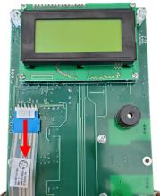
648 - 647 - Set LCD assembly in place; Remark:646
647 - Set LCD assembly in place
Set LCD assembly in place
646 - The LEDs on either side of the display might need to be slightly spread apart...
The LEDs on either side of the display might need to be slightly spread apart to allow for placement.
668 - 649 - Reinstall four (4) mounting screws; Remark:663
649 - Reinstall four (4) mounting screws
Reinstall four (4) mounting screws
663 - Use a small Phillips (PH1) screwdriver.
Use a small Phillips (PH1) screwdriver.
465 - 463 - Reconnect overlay button connector; Remark:464
462 - Caution : Correct placement of connectors and wiring is critical to proper operation.
Correct placement of connectors and wiring is critical to proper operation.
463 - Reconnect overlay button connector
Reconnect overlay button connector
768 - 468 - Set PRCB-472 board over mounting posts; Remark:765
468 - Set PRCB-472 board over mounting posts
Set PRCB-472 board over mounting posts
765 - Position overlay ribbon cable to avoid catching between PRCB-472 and mounting...
Position overlay ribbon cable to avoid catching between PRCB-472 and mounting hole.
473 - 471 - Reinstall four (4) mounting screws; Remark:472
471 - Reinstall four (4) mounting screws
Reinstall four (4) mounting screws
472 - Use a small Phillips (PH1) screwdriver.
Use a small Phillips (PH1) screwdriver.

484 - 482 - Replace GHA-472 board; Remark:483
482 - Replace GHA-472 board
Replace GHA-472 board
483 - Verify connectors are correctly aligned then press down.
Verify connectors are correctly aligned then press down.

490 - 488 - Reinstall GHA-472 board mounting nut; Remark:489
504 - Caution : Do not overtighten the mounting nut.
Do not overtighten the mounting nut.
488 - Reinstall GHA-472 board mounting nut
Reinstall GHA-472 board mounting nut
684 - 683 - Finish instrument assembly; Remark:
683 - Finish instrument assembly
Finish instrument assembly
500 - 498 - Reconnect all connectors except battery; Remark:499
498 - Reconnect all connectors except battery
Reconnect all connectors except battery
499 - Do not connect location 1.
Do not connect location 1.
503 - 305 - Reconnect battery; Remark:502
305 - Reconnect battery
Reconnect battery
308 - 307 - Replace front cover; Remark:
304 - Caution : Ensure all wiring is inside the instrument while replacing cover.
Ensure all wiring is inside the instrument while replacing cover.
307 - Replace front cover
Replace front cover
310 - 309 - Tighten four (4) cover screws; Remark:417
569 - Caution : Do not overtighten screws.
Do not overtighten screws.
309 - Tighten four (4) cover screws
Tighten four (4) cover screws
417 - Use a medium Phillips (PH2) screwdriver.
Use a medium Phillips (PH2) screwdriver.

320 - 319 - Perform operational test; Remark:347
319 - Perform operational test
Perform operational test
347 - Perform DET-HHD-RAP-RM01 PRM-470 Operational Test.
Perform DET-HHD-RAP-RM01 PRM-470 Operational Test.
322 - 321 - Document maintenance actions; Remark:
321 - Document maintenance actions
Document maintenance actions
2869 - 2585 - Document maintenance performed; Remark:2866
2585 - Document maintenance performed
Document maintenance performed
2866 - Record observations, times, and results for the maintenance report.
Record observations, times, and results for the maintenance report.
4706 - 4705 - Submit report; Remark:4864
4705 - Submit report
Submit report
4864 - As specified by management or contractual obligations.
As specified by management or contractual obligations.