Last Updated: 06/10/2025 1:36 AM
The following table lists all the components that make up the document.
Replace button overlay on PRM-470
Prior to arrival, notify operators concerning expected work and duration.
247 - 257 - Prepare instrument; Remark:
257 - Prepare instrument
Prepare instrument
607 - 205 - Disconnect charger; Remark:
205 - Disconnect charger
Disconnect charger
260 - 313 - Power off instrument; Remark:
313 - Power off instrument
Power off instrument
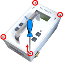
261 - 65 - Loosen four (4) cover screws; Remark:264
65 - Loosen four (4) cover screws
Loosen four (4) cover screws
264 - Use a medium Phillips (PH2) screwdriver. Screws do not need to be completely ...
Use a medium Phillips (PH2) screwdriver. Screws do not need to be completely removed.
263 - 262 - Remove instrument cover; Remark:413
2771 - Note : There are high-voltage detector circuit boards inside the instrument; however...
There are high-voltage detector circuit boards inside the instrument; however, they carry an extremely small current that does not pose a health risk.
262 - Remove instrument cover
Remove instrument cover
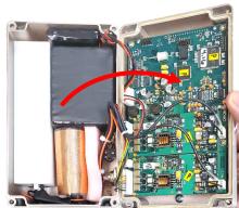
267 - 266 - Locate battery connection; Remark:272
3033 - Note : PRM-470 CGN models have an additional board and connectors not shown in remar...
PRM-470 CGN models have an additional board and connectors not shown in remark images.
266 - Locate battery connection
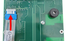
Locate battery connection
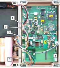
272 - Battery connection is labeled 1.
Battery connection is labeled 1.
271 - 270 - Disconnect battery; Remark:414
1345 - Note : It is good practice to ensure all cables and connectors are labeled prior to ...
It is good practice to ensure all cables and connectors are labeled prior to disconnection.
270 - Disconnect battery
Disconnect battery

443 - 442 - Disconnect remaining connectors; Remark:
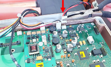
442 - Disconnect remaining connectors
Disconnect remaining connectors
618 - 615 - Uninstall PRCB-472 board; Remark:
615 - Uninstall PRCB-472 board
Uninstall PRCB-472 board
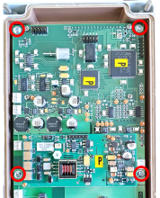
446 - 445 - Remove four (4) mounting screws; Remark:444
445 - Remove four (4) mounting screws
Remove four (4) mounting screws
444 - Use a small Phillips (PH1) screwdriver. Retain screws.
Use a small Phillips (PH1) screwdriver. Retain screws.
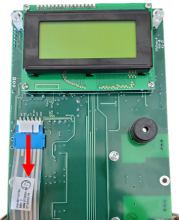
450 - 449 - Raise edge of PRCB-472 board to access underside; Remark:448
447 - Caution : Do not damage ribbon cable attached to the underside of PRCB-472.
Do not damage ribbon cable attached to the underside of PRCB-472.
449 - Raise edge of PRCB-472 board to access underside
Raise edge of PRCB-472 board to access underside
453 - 452 - Disconnect overlay button connector; Remark:451
452 - Disconnect overlay button connector
Disconnect overlay button connector
595 - 572 - Remove four (4) cover screws; Remark:594
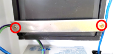
572 - Remove four (4) cover screws
Remove four (4) cover screws
594 - Completely remove screws by continuing to thread them out of the front cover....
Completely remove screws by continuing to thread them out of the front cover.
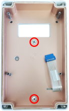
597 - 573 - Remove two (2) handle mounting screws; Remark:593
573 - Remove two (2) handle mounting screws
Remove two (2) handle mounting screws
593 - Use a medium Phillips screwdriver (PH2). Retain screws.
Use a medium Phillips screwdriver (PH2). Retain screws.
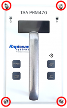
598 - 574 - Uninstall faulty overlay; Remark:
574 - Uninstall faulty overlay
Uninstall faulty overlay
599 - 575 - Peel off faulty overlay; Remark:592
575 - Peel off faulty overlay
Peel off faulty overlay
592 - Use a scraping tool or blade to begin. The overlay has two (2) layers. Verify...
Use a scraping tool or blade to begin. The overlay has two (2) layers. Verify both layers are being removed from the case.
600 - 576 - Clean case cover; Remark:591
576 - Clean case cover
Clean case cover
591 - Use scraper, adhesive remover, and rags to remove excess adhesive.
Use scraper, adhesive remover, and rags to remove excess adhesive.
601 - 580 - Install new button overlay; Remark:
580 - Install new button overlay
Install new button overlay
602 - 577 - Expose adhesive; Remark:590
577 - Expose adhesive
Expose adhesive
590 - Peel protective layer from new overlay.
Peel protective layer from new overlay.
603 - 578 - Feed overlay button connector through slot; Remark:589
578 - Feed overlay button connector through slot
Feed overlay button connector through slot
708 - 579 - Apply overlay to cover; Remark:707
579 - Apply overlay to cover
Apply overlay to cover
707 - Align holes for screws and LEDs.
Align holes for screws and LEDs.
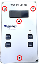
604 - 581 - Pull connector through slot; Remark:587
581 - Pull connector through slot
Pull connector through slot
587 - Overlay should be flat against the case.
Overlay should be flat against the case.
605 - 582 - Verify overlay is securely attached; Remark:586
582 - Verify overlay is securely attached
Verify overlay is securely attached
586 - Apply pressure over entire overlay to ensure contact with cover.
Apply pressure over entire overlay to ensure contact with cover.
303 - 302 - Reassemble instrument; Remark:
302 - Reassemble instrument
Reassemble instrument
709 - 583 - Reattach handle; Remark:585
583 - Reattach handle
Reattach handle
585 - Use a medium Phillips screwdriver (PH2).
Use a medium Phillips screwdriver (PH2).
710 - 584 - Reinsert four (4) assembly screws; Remark:596
584 - Reinsert four (4) assembly screws
Reinsert four (4) assembly screws
465 - 463 - Reconnect overlay button connector; Remark:464
462 - Caution : Correct placement of connectors and wiring is critical to proper operation.
Correct placement of connectors and wiring is critical to proper operation.
463 - Reconnect overlay button connector
Reconnect overlay button connector
470 - 468 - Set PRCB-472 board over mounting posts; Remark:469
468 - Set PRCB-472 board over mounting posts
Set PRCB-472 board over mounting posts
469 - Position ribbon cable to avoid obstructing PRCB-472 mounting hole.
Position ribbon cable to avoid obstructing PRCB-472 mounting hole.
473 - 471 - Reinstall four (4) mounting screws; Remark:472
471 - Reinstall four (4) mounting screws
Reinstall four (4) mounting screws
472 - Use a small Phillips (PH1) screwdriver.
Use a small Phillips (PH1) screwdriver.

500 - 498 - Reconnect all connectors except battery; Remark:499
498 - Reconnect all connectors except battery
Reconnect all connectors except battery
499 - Do not connect location 1.
Do not connect location 1.

306 - 305 - Reconnect battery; Remark:416
305 - Reconnect battery
Reconnect battery
308 - 307 - Replace front cover; Remark:
304 - Caution : Ensure all wiring is inside the instrument while replacing cover.
Ensure all wiring is inside the instrument while replacing cover.
307 - Replace front cover
Replace front cover
310 - 309 - Tighten four (4) cover screws; Remark:417
569 - Caution : Do not overtighten screws.
Do not overtighten screws.
309 - Tighten four (4) cover screws
Tighten four (4) cover screws
417 - Use a medium Phillips (PH2) screwdriver.
Use a medium Phillips (PH2) screwdriver.

359 - 319 - Perform operational test; Remark:347
319 - Perform operational test
Perform operational test
347 - Perform DET-HHD-RAP-RM01 PRM-470 Operational Test.
Perform DET-HHD-RAP-RM01 PRM-470 Operational Test.
322 - 321 - Document maintenance actions; Remark:
321 - Document maintenance actions
Document maintenance actions
2869 - 2585 - Document maintenance performed; Remark:2866
2585 - Document maintenance performed
Document maintenance performed
2866 - Record observations, times, and results for the maintenance report.
Record observations, times, and results for the maintenance report.
4706 - 4705 - Submit report; Remark:4864
4705 - Submit report
Submit report
4864 - As specified by management or contractual obligations.
As specified by management or contractual obligations.