Last Updated: 06/10/2025 1:36 AM
The following table lists all the components that make up the document.
Replace NHA-472 (neutron high voltage board) on PRM-470 CGN.
Prior to arrival, notify operators concerning expected work and duration.
247 - 257 - Prepare instrument; Remark:
257 - Prepare instrument
Prepare instrument

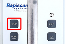
397 - 313 - Power off instrument; Remark:398
313 - Power off instrument
Power off instrument
398 - Press and hold the POWER button until instrument powers off....
Press and hold the POWER button until instrument powers off.
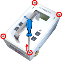
261 - 65 - Loosen four (4) cover screws; Remark:264
65 - Loosen four (4) cover screws
Loosen four (4) cover screws
264 - Use a medium Phillips (PH2) screwdriver. Screws do not need to be completely ...
Use a medium Phillips (PH2) screwdriver. Screws do not need to be completely removed.
263 - 262 - Remove instrument cover; Remark:413
2771 - Note : There are high-voltage detector circuit boards inside the instrument; however...
There are high-voltage detector circuit boards inside the instrument; however, they carry an extremely small current that does not pose a health risk.
262 - Remove instrument cover
Remove instrument cover
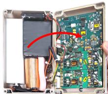
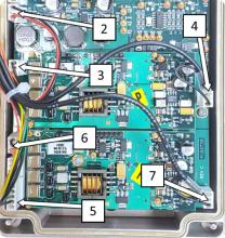
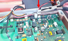
2734 - 266 - Locate battery connection; Remark:2733
3033 - Note : PRM-470 CGN models have an additional board and connectors not shown in remar...
PRM-470 CGN models have an additional board and connectors not shown in remark images.
266 - Locate battery connection
Locate battery connection
2733 - Battery connection is labeled 1.
Battery connection is labeled 1.
271 - 270 - Disconnect battery; Remark:414
1345 - Note : It is good practice to ensure all cables and connectors are labeled prior to ...
It is good practice to ensure all cables and connectors are labeled prior to disconnection.
270 - Disconnect battery
Disconnect battery

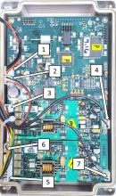
2737 - 2736 - Disconnect NHA-472 board wiring; Remark:2735
2736 - Disconnect NHA-472 board wiring
Disconnect NHA-472 board wiring
2735 - Remove connectors at locations 5, 6, and 7.
Remove connectors at locations 5, 6, and 7.

2739 - 2738 - Remove faulty NHA-472; Remark:
2738 - Remove faulty NHA-472
Remove faulty NHA-472
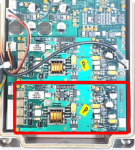
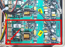
2742 - 2741 - Locate NHA-472 board; Remark:2740
2741 - Locate NHA-472 board
Locate NHA-472 board
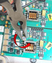
2745 - 2744 - Remove NHA-472 mounting nut; Remark:2743
2744 - Remove NHA-472 mounting nut
Remove NHA-472 mounting nut
2748 - 2747 - Remove NHA-472 board; Remark:2746
2747 - Remove NHA-472 board
Remove NHA-472 board
2746 - Gently pry up each side and lift.
Gently pry up each side and lift.


2750 - 2749 - Install new NHA-472; Remark:
2749 - Install new NHA-472
Install new NHA-472
2753 - 2752 - Mount new NHA-472; Remark:2751
2752 - Mount new NHA-472
Mount new NHA-472
2751 - Verify connectors are correctly aligned then press down.
Verify connectors are correctly aligned then press down.


2756 - 2755 - Reinstall mounting nut; Remark:2754
504 - Caution : Do not overtighten the mounting nut.
Do not overtighten the mounting nut.
2755 - Reinstall mounting nut
Reinstall mounting nut
2758 - 2757 - Reconnect wiring; Remark:
2757 - Reconnect wiring
Reconnect wiring
2761 - 2760 - Reconnect all connectors except battery; Remark:2759
2760 - Reconnect all connectors except battery
Reconnect all connectors except battery
2759 - Do not connect location 1.
Do not connect location 1.

2766 - 2764 - Adjust neutron high voltage; Remark:
2765 - Note : The same circuit boards are used for both gamma and neutron detectors; howeve...
The same circuit boards are used for both gamma and neutron detectors; however, the neutron detector board NHA-472 requires different voltage adjustments.
2764 - Adjust neutron high voltage
Adjust neutron high voltage
2770 - 2769 - Determine manufacturer of the neutron detector; Remark:2767
2769 - Determine manufacturer of the neutron detector
Determine manufacturer of the neutron detector
2767 - To access the neutron detector information, remove the moderator from the cas...
To access the neutron detector information, remove the moderator from the case and slide the neutron detector out.


2768 - Detector information is printed on the detector. There are two (2) common neu...
Detector information is printed on the detector. There are two (2) common neutron detector manufacturers: GE Reuter-Stokes and LND. RS indicates GE Reuter-Stokes.

2772 - 220 - Power on instrument; Remark:228
2771 - Note : There are high-voltage detector circuit boards inside the instrument; however...
There are high-voltage detector circuit boards inside the instrument; however, they carry an extremely small current that does not pose a health risk.
220 - Power on instrument
Power on instrument
228 - Press POWER button until the display turns on.
Press POWER button until the display turns on.
2777 - 2776 - Connect HV probe to DMM; Remark:2774
2776 - Connect HV probe to DMM
Connect HV probe to DMM
2774 - Use Fluke 80K-40 High Voltage Probe and Fluke 179 DMM. The GND tab should lin...
Use Fluke 80K-40 High Voltage Probe and Fluke 179 DMM. The GND tab should line up with the COM position.

2658 - 2566 - Switch DMM to DC voltage; Remark:2613
2566 - Switch DMM to DC voltage
Switch DMM to DC voltage

2785 - 2567 - Locate ground test point; Remark:2782
2567 - Locate ground test point
Locate ground test point
2782 - The neutron ground TP38 is located on the NHA-472 neutron board and might not...
The neutron ground TP38 is located on the NHA-472 neutron board and might not be clearly labeled.
2790 - 2789 - Connect HV probe to ground; Remark:2787
2789 - Connect HV probe to ground
Connect HV probe to ground
2787 - The ground connector for the HV probe may be directly connected to the ground...
The ground connector for the HV probe may be directly connected to the ground test point.
2788 - It may be easier to use a separate test lead (jumper wire) and connect the HV...
It may be easier to use a separate test lead (jumper wire) and connect the HV probe ground to the test lead.

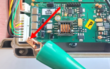
2794 - 2792 - Locate high voltage test point; Remark:2791
2793 - Warning : The test point has high voltage. Only contact the test point with the high vo...
The test point has high voltage. Only contact the test point with the high voltage probe.
2792 - Locate high voltage test point
Locate high voltage test point
2791 - The neutron high voltage TP34 is located on the NHA-472 neutron board and mig...
The neutron high voltage TP34 is located on the NHA-472 neutron board and might not be clearly labeled.

2797 - 2796 - Contact HV probe to test point; Remark:2795
2796 - Contact HV probe to test point
Contact HV probe to test point
2795 - Contact TP34 (not labeled) with tip of red HV probe.
Contact TP34 (not labeled) with tip of red HV probe.
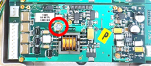
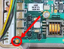
2874 - 2873 - Locate neutron high voltage adjustment; Remark:2872
2873 - Locate neutron high voltage adjustment
Locate neutron high voltage adjustment
2872 - R10 on the NHA-472 neutron board is used to adjust the high voltage for the n...
R10 on the NHA-472 neutron board is used to adjust the high voltage for the neutron detector.
2885 - 2881 - Adjust neutron high voltage; Remark:2875
2884 - Standard : High voltage for a GE Reuter-Stokes neutron detection is 990 Volts. High volt...
High voltage for a GE Reuter-Stokes neutron detection is 990 Volts. High voltage for a LND neutron detector is 1075 Volts.
2881 - Adjust neutron high voltage
Adjust neutron high voltage
2875 - Use precision slotted (tweaker) screwdriver to adjust R10. The voltage should...
Use precision slotted (tweaker) screwdriver to adjust R10. The voltage should match the manufacturer’s recommendation.
GE Reuter-Stokes: 990 Volts
LND: 1075 Volts
2878 - The number indicated on the DMM must be multiplied by 1000 if the Fluke 80K-4...
The number indicated on the DMM must be multiplied by 1000 if the Fluke 80K-40 probe is being used.

2889 - 2888 - Remove HV probe leads; Remark:
2888 - Remove HV probe leads
Remove HV probe leads
2893 - 2892 - Locate neutron stage 2 gain adjustment; Remark:2891
2892 - Locate neutron stage 2 gain adjustment
Locate neutron stage 2 gain adjustment
2891 - R17 on the NHA-472 neutron board is used to adjust the stage 2 gain.
R17 on the NHA-472 neutron board is used to adjust the stage 2 gain.
2896 - 2895 - Set stage 2 gain at maximum; Remark:2894
2895 - Set stage 2 gain at maximum
Set stage 2 gain at maximum
2894 - Use precision slotted (tweaker) screwdriver to rotate R17 10 full turns clock...
Use precision slotted (tweaker) screwdriver to rotate R17 10 full turns clockwise.

303 - 302 - Reassemble instrument; Remark:
302 - Reassemble instrument
Reassemble instrument
2898 - 307 - Replace front cover; Remark:2897
304 - Caution : Ensure all wiring is inside the instrument while replacing cover.
Ensure all wiring is inside the instrument while replacing cover.
307 - Replace front cover
Replace front cover

310 - 309 - Tighten four (4) cover screws; Remark:417
569 - Caution : Do not overtighten screws.
Do not overtighten screws.
309 - Tighten four (4) cover screws
Tighten four (4) cover screws
417 - Use a medium Phillips (PH2) screwdriver.
Use a medium Phillips (PH2) screwdriver.

320 - 319 - Perform operational test; Remark:347
319 - Perform operational test
Perform operational test
347 - Perform DET-HHD-RAP-RM01 PRM-470 Operational Test.
Perform DET-HHD-RAP-RM01 PRM-470 Operational Test.
322 - 321 - Document maintenance actions; Remark:
321 - Document maintenance actions
Document maintenance actions
2869 - 2585 - Document maintenance performed; Remark:2866
2585 - Document maintenance performed
Document maintenance performed
2866 - Record observations, times, and results for the maintenance report.
Record observations, times, and results for the maintenance report.
4706 - 4705 - Submit report; Remark:4864
4705 - Submit report
Submit report
4864 - As specified by management or contractual obligations.
As specified by management or contractual obligations.