Last Updated: 06/08/2025 1:35 AM
The following table lists all the components that make up the document.
Perform a gamma electronic alignment on the PRM-470. Knowledge of the AMPTEK software DppMCA is required.
247 - 257 - Prepare instrument; Remark:
257 - Prepare instrument
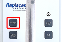
Prepare instrument

261 - 65 - Loosen four (4) cover screws; Remark:264
65 - Loosen four (4) cover screws
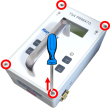
Loosen four (4) cover screws
264 - Use a medium Phillips (PH2) screwdriver. Screws do not need to be completely ...
Use a medium Phillips (PH2) screwdriver. Screws do not need to be completely removed.
2642 - 262 - Remove instrument cover; Remark:2631
2634 - Warning : Do not touch circuit board components as there are high voltage energized tes...
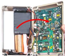
Do not touch circuit board components as there are high voltage energized test points when the instrument is powered on. The current is not sufficient to cause severe bodily harm but can result in a shock.
262 - Remove instrument cover
Remove instrument cover
2643 - 2551 - Connect Multichannel Analyzer (MCA); Remark:
2551 - Connect Multichannel Analyzer (MCA)
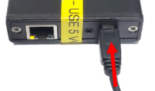
Connect Multichannel Analyzer (MCA)
2644 - 2552 - Connect MCA to computer; Remark:2630
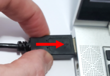
2552 - Connect MCA to computer
Connect MCA to computer
2630 - Use provided Mini-USB [universal serial bus] to USB cable.
Use provided Mini-USB [universal serial bus] to USB cable.
2645 - 2553 - Attach test leads to MCA; Remark:2629
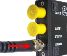
2553 - Attach test leads to MCA
Attach test leads to MCA
2629 - Connect to the SIGNAL input.
Connect to the SIGNAL input.
2646 - 2554 - Collect pre-alignment Spectra; Remark:
2554 - Collect pre-alignment Spectra
Collect pre-alignment Spectra

2648 - 2556 - Verify MCA settings; Remark:2626
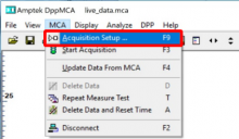
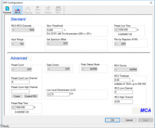
2556 - Verify MCA settings
Verify MCA settings
2626 - Settings should match the image below.
Settings should match the image below.
2649 - 2557 - Place Cs-137 source on gamma detector; Remark:2625
2557 - Place Cs-137 source on gamma detector
Place Cs-137 source on gamma detector
2625 - Center the source on the detector.
Center the source on the detector.

2650 - 2558 - Connect leads to stage 1 test points; Remark:2624
2558 - Connect leads to stage 1 test points
Connect leads to stage 1 test points
2624 - Black test lead connects to TP20. Red test lead connects to TP1.
Black test lead connects to TP20. Red test lead connects to TP1.

2651 - 2559 - Collect stage 1 spectrum; Remark:2622
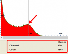
2635 - Standard : At least 2,000 counts should be recorded on the peak channel.
At least 2,000 counts should be recorded on the peak channel.
2636 - Note : Hot keys for DppMCA software: “A” will clear spectrum and restart acquisi...
Hot keys for DppMCA software: “A” will clear spectrum and restart acquisition; “F3” will stop/start acquisition.
2559 - Collect stage 1 spectrum
Collect stage 1 spectrum
2622 - The traffic light icon will start/stop data acquisition.
The traffic light icon will start/stop data acquisition.
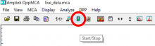
2623 - Placing the cursor at the peak location will aid in monitoring the counts in ...
Placing the cursor at the peak location will aid in monitoring the counts in that channel.
2652 - 2560 - Save stage 1 spectrum; Remark:2620
2637 - Standard : Use the following file naming convention: CO_SITE_MO_SN_STG_PP CO =...
Use the following file naming convention: CO_SITE_MO_SN_STG_PP
CO = NSDD standard country code
SITE = NSDD site code
MO = PRM-470 model number (either CG or CGN)
SN = PRM-470 serial number
STG = stage gain (1ST or 2ND)
PP = Measurement before or after gain adjustment (PRE or POST)
Example: US_Richland_CG_1045_1ST_PRE
2560 - Save stage 1 spectrum
Save stage 1 spectrum
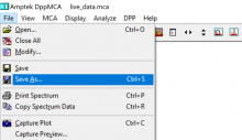
2621 - Use the correct file naming convention. Example: US_Richland_CG_102...
Use the correct file naming convention.
Example: US_Richland_CG_1024_1ST_PRE
2653 - 2561 - Connect leads to stage 2 test point; Remark:2619
2561 - Connect leads to stage 2 test point
Connect leads to stage 2 test point
2619 - Red test lead connects to TP2.
Red test lead connects to TP2.

2654 - 2562 - Collect stage 2 spectrum; Remark:2617
2635 - Standard : At least 2,000 counts should be recorded on the peak channel.
At least 2,000 counts should be recorded on the peak channel.
2636 - Note : Hot keys for DppMCA software: “A” will clear spectrum and restart acquisi...
Hot keys for DppMCA software: “A” will clear spectrum and restart acquisition; “F3” will stop/start acquisition.
2562 - Collect stage 2 spectrum
Collect stage 2 spectrum
2617 - Start data collection.
Start data collection.
2618 - Placing the cursor at the peak location will aid in monitoring the counts in ...
Placing the cursor at the peak location will aid in monitoring the counts in that channel.

2655 - 2563 - Save stage 2 spectrum; Remark:2616
2563 - Save stage 2 spectrum
Save stage 2 spectrum
2616 - Use the correct file naming convention. Example: US_Richland_CG_102...
Use the correct file naming convention.
Example: US_Richland_CG_1024_2ND_PRE
2656 - 2564 - Measure pre-alignment high voltage; Remark:
2564 - Measure pre-alignment high voltage
Measure pre-alignment high voltage
2657 - 2565 - Connect HV probe to DMM; Remark:2614
2565 - Connect HV probe to DMM
Connect HV probe to DMM
2614 - Use Fluke 80K-40 high voltage (HV) probe and Fluke 179 DMM.
Use Fluke 80K-40 high voltage (HV) probe and Fluke 179 DMM.
2658 - 2566 - Switch DMM to DC voltage; Remark:2613
2566 - Switch DMM to DC voltage
Switch DMM to DC voltage

2659 - 2567 - Locate ground test point; Remark:2610
2567 - Locate ground test point
Locate ground test point
2610 - The ground TP38 is located on the GHA-472 gamma board and might not be clearl...
The ground TP38 is located on the GHA-472 gamma board and might not be clearly labeled.
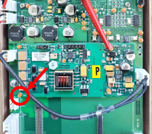
2660 - 2568 - Connect HV probe to ground; Remark:2609
2568 - Connect HV probe to ground
Connect HV probe to ground
2609 - Connect black test lead of HV probe to TP38. Verify good connection.
Connect black test lead of HV probe to TP38. Verify good connection.
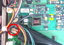
2661 - 2569 - Locate HV test point; Remark:2607
2569 - Locate HV test point
Locate HV test point
2607 - The HV TP34 is located on the GHA-472 gamma board and might not be clearly la...
The HV TP34 is located on the GHA-472 gamma board and might not be clearly labeled.

2662 - 2570 - Connect HV probe to test point; Remark:2605
2638 - Warning : The test point has high voltage. Only contact the test point with the high vo...
The test point has high voltage. Only contact the test point with the high voltage probe.
2570 - Connect HV probe to test point
Connect HV probe to test point
2605 - Contact TP34 with tip of red HV probe.
Contact TP34 with tip of red HV probe.

2663 - 2571 - Document voltage; Remark:2589
2639 - Standard : Typical values are between 650 and 850 Volts DC. Older units might have highe...
Typical values are between 650 and 850 Volts DC. Older units might have higher voltages. Maximum high voltage should be no more than 1250 Volts.
2571 - Document voltage
Document voltage
2589 - The number indicated on the DMM must be multiplied by 1000 if the 80K-40 prob...
The number indicated on the DMM must be multiplied by 1000 if the 80K-40 probe is being used.
Example: 0.7453 x 1000 = 745.3 Volts DC.

2664 - 2572 - Remove HV probe from PRM-470; Remark:
2572 - Remove HV probe from PRM-470
Remove HV probe from PRM-470
2665 - 2573 - Adjust gains; Remark:
2573 - Adjust gains
Adjust gains
2666 - 2574 - Connect leads to stage 1 test points; Remark:2602
2574 - Connect leads to stage 1 test points
Connect leads to stage 1 test points
2602 - Black test lead connects to TP20. Red test lead connects to TP1.
Black test lead connects to TP20. Red test lead connects to TP1.

2667 - 2575 - Verify Cs-137 source is on center of gamma detector; Remark:2601
2575 - Verify Cs-137 source is on center of gamma detector
Verify Cs-137 source is on center of gamma detector
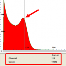
2668 - 2576 - Adjust stage 1 gain; Remark:2599
2640 - Standard : 1st stage gain = Peak location should be at channel 115 +/- 3 channels.
1st stage gain = Peak location should be at channel 115 +/- 3 channels.
2576 - Adjust stage 1 gain
Adjust stage 1 gain
2599 - Use precision slotted (tweaker) screwdriver to adjust R10 until peak is cente...
Use precision slotted (tweaker) screwdriver to adjust R10 until peak is centered on channel 115. If no peak is visible, try turning R10 several turns in both directions until the peak appears.

2669 - 2559 - Collect stage 1 spectrum; Remark:2598
2635 - Standard : At least 2,000 counts should be recorded on the peak channel.
At least 2,000 counts should be recorded on the peak channel.
2559 - Collect stage 1 spectrum
Collect stage 1 spectrum
2598 - Place the cursor at channel 115 to monitor the counts.
Place the cursor at channel 115 to monitor the counts.
2670 - 2560 - Save stage 1 spectrum; Remark:2597
2560 - Save stage 1 spectrum
Save stage 1 spectrum
2597 - Use the correct file naming convention. Example: US_Richland_CG_102...
Use the correct file naming convention.
Example: US_Richland_CG_1024_1ST_POST
2671 - 2577 - Connect to stage 2 test point; Remark:2596
2577 - Connect to stage 2 test point
Connect to stage 2 test point
2596 - Move red test lead to TP2.
Move red test lead to TP2.
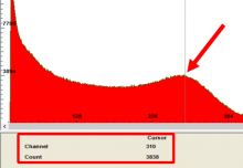
2672 - 2578 - Adjust stage 2 gain; Remark:2593
2641 - Standard : 2nd stage gain = Peak location should be at channel 310 +/- 5 channels.
2nd stage gain = Peak location should be at channel 310 +/- 5 channels.
2578 - Adjust stage 2 gain
Adjust stage 2 gain
2593 - Use Tweaker to adjust R17 (may not be labeled on board) until peak is centere...
Use Tweaker to adjust R17 (may not be labeled on board) until peak is centered on 310 Channel. If no peak is visible, try turning R17 several turns in both directions until the peak appears.

2673 - 2562 - Collect stage 2 spectrum; Remark:2592
2635 - Standard : At least 2,000 counts should be recorded on the peak channel.
At least 2,000 counts should be recorded on the peak channel.
2562 - Collect stage 2 spectrum
Collect stage 2 spectrum
2592 - Place the cursor at channel 310 to monitor the counts.
Place the cursor at channel 310 to monitor the counts.
2674 - 2563 - Save stage 2 spectrum; Remark:2591
2563 - Save stage 2 spectrum
Save stage 2 spectrum
2591 - Use the correct file naming convention. Example: US_Richland_CG_102...
Use the correct file naming convention.
Example: US_Richland_CG_1024_2ND_POST
2675 - 2579 - Remove test leads; Remark:
2579 - Remove test leads
Remove test leads
2676 - 2580 - Disconnect MCA; Remark:
2580 - Disconnect MCA
Disconnect MCA
2677 - 2581 - Remove radioactive source; Remark:
2581 - Remove radioactive source
Remove radioactive source
2678 - 2582 - Measure post-alignment high voltage; Remark:
2582 - Measure post-alignment high voltage
Measure post-alignment high voltage
2679 - 2583 - Measure high voltage; Remark:2590
2638 - Warning : The test point has high voltage. Only contact the test point with the high vo...
The test point has high voltage. Only contact the test point with the high voltage probe.
2583 - Measure high voltage
Measure high voltage
2590 - Repeat high voltage measurement steps provided earlier in this procedure....
Repeat high voltage measurement steps provided earlier in this procedure.
2680 - 2571 - Document voltage; Remark:2589
2639 - Standard : Typical values are between 650 and 850 Volts DC. Older units might have highe...
Typical values are between 650 and 850 Volts DC. Older units might have higher voltages. Maximum high voltage should be no more than 1250 Volts.
2571 - Document voltage
Document voltage
2589 - The number indicated on the DMM must be multiplied by 1000 if the 80K-40 prob...
The number indicated on the DMM must be multiplied by 1000 if the 80K-40 probe is being used.
Example: 0.7453 x 1000 = 745.3 Volts DC.
2681 - 2572 - Remove HV probe from PRM-470; Remark:2588
2572 - Remove HV probe from PRM-470
Remove HV probe from PRM-470
2588 - Power off DMM. Carefully remove test leads.
Power off DMM. Carefully remove test leads.
303 - 302 - Reassemble instrument; Remark:
302 - Reassemble instrument
Reassemble instrument
2684 - 307 - Replace front cover; Remark:
304 - Caution : Ensure all wiring is inside the instrument while replacing cover.
Ensure all wiring is inside the instrument while replacing cover.
307 - Replace front cover
Replace front cover
310 - 309 - Tighten four (4) cover screws; Remark:417
569 - Caution : Do not overtighten screws.
Do not overtighten screws.
309 - Tighten four (4) cover screws
Tighten four (4) cover screws
417 - Use a medium Phillips (PH2) screwdriver.
Use a medium Phillips (PH2) screwdriver.

320 - 319 - Perform operational test; Remark:347
319 - Perform operational test
Perform operational test
347 - Perform DET-HHD-RAP-RM01 PRM-470 Operational Test.
Perform DET-HHD-RAP-RM01 PRM-470 Operational Test.
2682 - 2584 - Perform efficiency test; Remark:2587
2584 - Perform efficiency test
Perform efficiency test
2587 - DET-HHD-RAP-RM05, PRM-470 Efficiency Test
DET-HHD-RAP-RM05, PRM-470 Efficiency Test
322 - 321 - Document maintenance actions; Remark:
321 - Document maintenance actions
Document maintenance actions
2869 - 2585 - Document maintenance performed; Remark:2866
2585 - Document maintenance performed
Document maintenance performed
2866 - Record observations, times, and results for the maintenance report.
Record observations, times, and results for the maintenance report.
4706 - 4705 - Submit report; Remark:4864
4705 - Submit report
Submit report
4864 - As specified by management or contractual obligations.
As specified by management or contractual obligations.