Last Updated: 06/18/2025 1:43 AM
The following table lists all the components that make up the document.
Install the BEA IXIO-DT1 occupancy sensor on the pedestrian radiation portal monitor (RPM). The existing Visonic SPY-2 infrared curtain sensor is abandoned in place.
Verify occupancy sensor functionality
Prior to arrival, notify operators concerning expected work, duration, and anticipated alarms and fault indications.
Updated LD-260 images to re-usable standardized content. Updated instructions to standardized re-usable content.
7264 - 1401 - Establish Initial Conditions; Remark:
1401 - Establish Initial Conditions
Establish Initial Conditions
7622 - 7592 - Inform system operators; Remark:11335
7592 - Inform system operators
Inform system operators
11335 - Upon arrival, brief system operators on expected work, duration, anticipated ...
Upon arrival, brief system operators on expected work, duration, anticipated alarms, and fault indications before starting work.
7452 - 7231 - Close lane; Remark:7415
7231 - Close lane
Close lane
7415 - Re-route pedestrian traffic.
Re-route pedestrian traffic.
7269 - 7232 - Open RPM door; Remark:7234
7232 - Open RPM door
Open RPM door
7234 - Open all doors needed to access components.
Open all doors needed to access components.
7755 - 7679 - Disconnect Ethernet; Remark:11336
7680 - Caution : Make sure to press release button on back of Ethernet cable before removing.
Make sure to press release button on back of Ethernet cable before removing.
7679 - Disconnect Ethernet
Disconnect Ethernet
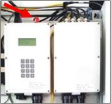
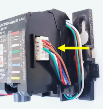
11336 - Locate Ethernet connector on top of SC-770 controller. Press release button o...
Locate Ethernet connector on top of SC-770 controller. Press release button on back of connector. Pull connector.
7270 - 7235 - Power off RPM; Remark:7236
7235 - Power off RPM
Power off RPM
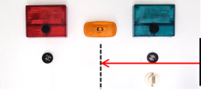
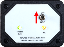
7236 - Move LD-260 switch to OFF position. The PWR ON
Move LD-260 switch to OFF position. The PWR ON LED will turn off.

7454 - 7290 - Disable tamper switches; Remark:7416
7290 - Disable tamper switches
Disable tamper switches
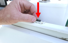
7416 - Use a magnet to disable tamper switches for all open doors. Use adhesive tape...
Use a magnet to disable tamper switches for all open doors. Use adhesive tape to disable older mechanical switches.
8561 - 7291 - Disable both infrared occupancy sensors; Remark:8514
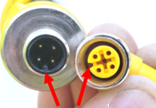
5291 - Note : It is good practice to verify all cables and connectors are labeled prior to ...
It is good practice to verify all cables and connectors are labeled prior to disconnection.
7291 - Disable both infrared occupancy sensors
Disable both infrared occupancy sensors
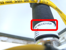
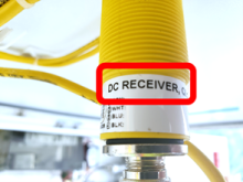
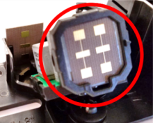
8514 - Verify sensors mounted in control pillar door are receivers.
Verify sensors mounted in control pillar door are receivers.
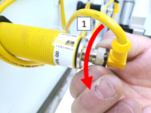
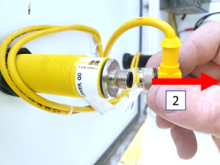
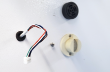
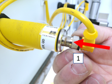
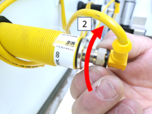
9205 - To disconnect sensor cable, turn collar counterclockwise and pull away from s...
To disconnect sensor cable, turn collar counterclockwise and pull away from sensor.
7479 - 7417 - Prepare New Occupancy Sensor; Remark:
7417 - Prepare New Occupancy Sensor
Prepare New Occupancy Sensor
7456 - 7418 - Remove cover from new occupancy sensor; Remark:7419
7418 - Remove cover from new occupancy sensor
Remove cover from new occupancy sensor
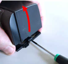
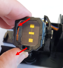
7419 - Use a slotted screwdriver to pry the cover off from the side.
Use a slotted screwdriver to pry the cover off from the side.
7457 - 7420 - Verify narrow field radar antenna is installed; Remark:7421
7420 - Verify narrow field radar antenna is installed
Verify narrow field radar antenna is installed
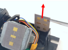
7421 - The IXIO-DT1 should come with the narrow field antenna installed.
The IXIO-DT1 should come with the narrow field antenna installed.
8901 - If needed, the antenna can be changed. Remove cover. Install narrow field ant...
If needed, the antenna can be changed. Remove cover. Install narrow field antenna stored in slot behind antenna mount. Replace cover.
8889 - 8888 - Prepare Mounting Holes; Remark:
8888 - Prepare Mounting Holes
Prepare Mounting Holes
8884 - 8883 - Mark mounting hole height; Remark:8882
8883 - Mark mounting hole height
Mark mounting hole height
8882 - Use erasable marker or pencil to draw a level horizontal line. Mounting hole ...
Use erasable marker or pencil to draw a level horizontal line. Mounting hole height is 35 cm from top of cabinet door.
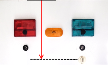
8886 - 8879 - Mark centerline of pedestrian monitor door; Remark:8878
8879 - Mark centerline of pedestrian monitor door
Mark centerline of pedestrian monitor door
8878 - Use erasable marker or pencil to draw a vertical line.
Use erasable marker or pencil to draw a vertical line.
8885 - 8881 - Attach mounting template; Remark:8880
8881 - Attach mounting template
Attach mounting template
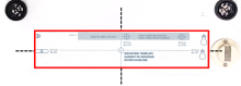
8880 - Template provided with the IXIO-DT1 has a self-adhesive backing. Template may...
Template provided with the IXIO-DT1 has a self-adhesive backing. Template may differ from picture shown. Match template lines with vertical and horizontal marks.
8887 - 8877 - Mark location of 3.2-mm (1/8-inch) mounting holes; Remark:8876
8904 - Caution : Ensure placement of mounting holes will not interfere with internal wiring in...
Ensure placement of mounting holes will not interfere with internal wiring in the cabinet.
8877 - Mark location of 3.2-mm (1/8-inch) mounting holes
Mark location of 3.2-mm (1/8-inch) mounting holes
8876 - If available, use a center punch and hammer to create a dimple at each mounti...
If available, use a center punch and hammer to create a dimple at each mounting hole location.
8905 - 8903 - Mark location of 8-mm (5/16-inch) hole for wire passage; Remark:8902
8903 - Mark location of 8-mm (5/16-inch) hole for wire passage
Mark location of 8-mm (5/16-inch) hole for wire passage
8902 - If available, use a center punch and hammer to create a dimple at center of w...
If available, use a center punch and hammer to create a dimple at center of wire passage hole.
8946 - 8945 - Drill Installation Holes; Remark:
8945 - Drill Installation Holes
Drill Installation Holes
8939 - 8938 - Hold or block the door in an open position; Remark:
8938 - Hold or block the door in an open position
Hold or block the door in an open position
8940 - 8935 - Drill two (2) mounting holes; Remark:8934
8936 - Warning : Wear protective gloves and eyewear when drilling into cabinet door.
Wear protective gloves and eyewear when drilling into cabinet door.
8937 - Caution : Do not damage interior of RPM when drilling holes.
Do not damage interior of RPM when drilling holes.
8935 - Drill two (2) mounting holes
Drill two (2) mounting holes
8934 - Use a 3.2-mm (1/8-inch) drill bit.
Use a 3.2-mm (1/8-inch) drill bit.
8941 - 8933 - Drill wire passage hole; Remark:8932
8933 - Drill wire passage hole
Drill wire passage hole
8932 - Use an 8-mm (5/16-inch) drill bit.
Use an 8-mm (5/16-inch) drill bit.
8942 - 8931 - Clean newly drilled holes; Remark:8930
8931 - Clean newly drilled holes
Clean newly drilled holes
8930 - Use the deburring tool
Use the deburring tool
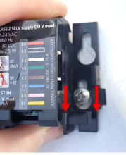
8943 - 8929 - Partially insert two (2) screws into mounting holes; Remark:8928
8929 - Partially insert two (2) screws into mounting holes
Partially insert two (2) screws into mounting holes
8928 - Mounting screws are included in the IXIO-DT-1 kit. Do not fully tighten screw...
Mounting screws are included in the IXIO-DT-1 kit. Do not fully tighten screws. Enough room should be available to slide the sensor in place.
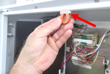
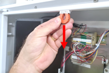
8944 - 8926 - Insert rubber grommet in wire passage hole; Remark:8925
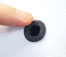
8927 - Note : Protecting wires with a rubber grommet is critical to preventing damage to wi...
Protecting wires with a rubber grommet is critical to preventing damage to wiring and possible equipment malfunctions.
8926 - Insert rubber grommet in wire passage hole
Insert rubber grommet in wire passage hole
8925 - rubber grommet
8924 - 8923 - Install IXIO-DT1 Sensor; Remark:
8923 - Install IXIO-DT1 Sensor
Install IXIO-DT1 Sensor
8918 - 8917 - Feed wiring connector through grommet; Remark:8915
8917 - Feed wiring connector through grommet
Feed wiring connector through grommet
8915 - The wiring assembly is included in the IXIO-DT1 kit. Feed loose end of wiring...
The wiring assembly is included in the IXIO-DT1 kit. Feed loose end of wiring assembly through hole.
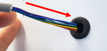
8916 - Leave approximately 15 cm (6 in) of wire remaining outside of cabinet.
Leave approximately 15 cm (6 in) of wire remaining outside of cabinet.
8919 - 8914 - Mount new sensor; Remark:8912
8914 - Mount new sensor
Mount new sensor
8912 - First, slide left side onto mounting screw.
First, slide left side onto mounting screw.
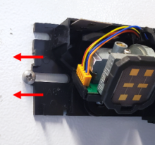
8913 - Then, place right side over mounting screw and push down.
Then, place right side over mounting screw and push down.
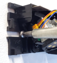
8920 - 8911 - Tighten two (2) mounting screws; Remark:8910
8911 - Tighten two (2) mounting screws
Tighten two (2) mounting screws
8910 - Use medium Phillips (PH2) screwdriver. Take care not to overtighten.
Use medium Phillips (PH2) screwdriver. Take care not to overtighten.
8921 - 8909 - Route wiring through clamp and connect; Remark:8908
8909 - Route wiring through clamp and connect
Route wiring through clamp and connect
8922 - 8907 - Adjust angle of the radar antenna; Remark:8906
8907 - Adjust angle of the radar antenna
Adjust angle of the radar antenna
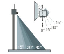
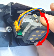
8906 - The angle is adjusted by manually rotating the antenna up or down. The defaul...
The angle is adjusted by manually rotating the antenna up or down. The default angle is approximately 15 degrees.
8970 - 8969 - Connect Wiring to RPM; Remark:
8969 - Connect Wiring to RPM
Connect Wiring to RPM
8963 - 8962 - Disconnect existing SPY-2 wiring; Remark:8961
7351 - Note : It is good practice to verify all cables and connectors are labeled prior to ...
It is good practice to verify all cables and connectors are labeled prior to disconnection.
8962 - Disconnect existing SPY-2 wiring
Disconnect existing SPY-2 wiring
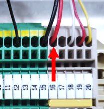
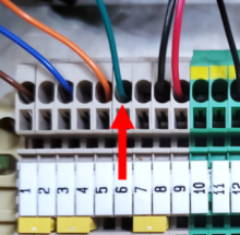
8961 - Do not remove existing occupancy sensor from door panel. Disconnect SPY-2 wir...
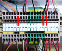
Do not remove existing occupancy sensor from door panel. Disconnect SPY-2 wiring from terminal block 2 (TB2). Existing wiring is normally connected at pin 16, pin 15, and pin 6.
8964 - 8960 - Route new cable to TB2; Remark:8959
8960 - Route new cable to TB2
Route new cable to TB2
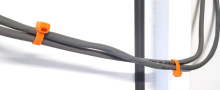
8959 - New IXIO-DT1 cable should be routed along existing SPY-2 cable. Cable ties ma...
New IXIO-DT1 cable should be routed along existing SPY-2 cable. Cable ties may be used to secure new wiring to existing wiring.
8965 - 8958 - Connect red wire to TB2, Pin 16; Remark:8956
7263 - Caution : Correct placement of connectors and wiring is critical to proper operation.
Correct placement of connectors and wiring is critical to proper operation.
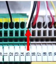
8958 - Connect red wire to TB2, Pin 16
Connect red wire to TB2, Pin 16
8956 - Red is power (+12 VDC) wire.
Red is power (+12 VDC) wire.
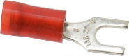
8957 - For models with older terminal blocks, it may be necessary to use a fork conn...
For models with older terminal blocks, it may be necessary to use a fork connector.

8966 - 8955 - Connect both black and white wires to TB2, Pin 15; Remark:8954
8955 - Connect both black and white wires to TB2, Pin 15
Connect both black and white wires to TB2, Pin 15
8954 - Black is the ground wire. White is the common wire
Black is the ground wire. White is the common wire
8967 - 8953 - Connect green wire to TB2, Pin 6; Remark:8952
8953 - Connect green wire to TB2, Pin 6
Connect green wire to TB2, Pin 6
8952 - Green is the occupancy signal to the SCA-775 module.
Green is the occupancy signal to the SCA-775 module.
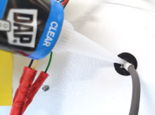
8968 - 8951 - Apply sealant if needed; Remark:8950
8951 - Apply sealant if needed
Apply sealant if needed
8950 - Access wire penetration hole from back of the RPM door.
Access wire penetration hole from back of the RPM door.
7279 - 7249 - Return equipment to normal operating condition; Remark:
7249 - Return equipment to normal operating condition
Return equipment to normal operating condition
8949 - 8948 - Hold door open; Remark:8947
8948 - Hold door open
Hold door open
8947 - Do not move door. Door must remain stationary to prevent occupancy.
Do not move door. Door must remain stationary to prevent occupancy.
7280 - 7250 - Power on RPM; Remark:7251
7250 - Power on RPM
Power on RPM
7251 - Move LD-260 switch to ON position. The LED PWR ON
Move LD-260 switch to ON position. The LED PWR ON will illuminate.
7281 - 7252 - Verify RPM start-up; Remark:7253
7252 - Verify RPM start-up
Verify RPM start-up
7253 - RPM will perform a power on self-test (POST) and collect a background radiati...
RPM will perform a power on self-test (POST) and collect a background radiation measurement.
7470 - 7442 - Generate occupancy; Remark:7443
7442 - Generate occupancy
Generate occupancy
7443 - Create motion in front of occupancy sensor. While holding the door open and s...
Create motion in front of occupancy sensor. While holding the door open and still, wave a hand or walk in front of the sensor.
7471 - 7444 - Verify occupancy sensor functionality; Remark:7445
7444 - Verify occupancy sensor functionality
Verify occupancy sensor functionality
7445 - IXIO-DT1 green sensor light will illuminate.
IXIO-DT1 green sensor light will illuminate.
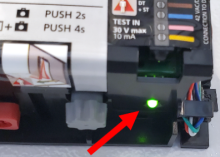
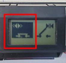
8973 - Left latch on the LCD screen will indicate a “closed” circuit.
Left latch on the LCD screen will indicate a “closed” circuit.
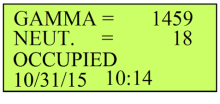
8974 - SC-770 status will read “OCCUPIED”.
SC-770 status will read “OCCUPIED”.
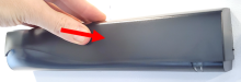
7472 - 7446 - Install sensor cover; Remark:7447
7446 - Install sensor cover
Install sensor cover
7447 - The cover should snap into place.
The cover should snap into place.
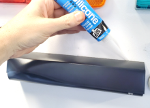
7473 - 7448 - If needed, apply sealant; Remark:7449
7448 - If needed, apply sealant
If needed, apply sealant
7449 - If used outdoors, sealant should be applied to top and sides of cover. Do not...
If used outdoors, sealant should be applied to top and sides of cover. Do not apply sealant along bottom of cover. Remove excess silicone with mineral spirits and rags.
8587 - 7305 - Enable both infrared occupancy sensors; Remark:8559
5553 - Caution : Correct placement of connectors and wiring is critical to proper operation.
Correct placement of connectors and wiring is critical to proper operation.
7305 - Enable both infrared occupancy sensors
Enable both infrared occupancy sensors
8559 - To reconnect sensor cable, align connectors, push towards sensor, and turn co...
To reconnect sensor cable, align connectors, push towards sensor, and turn collar clockwise.
7474 - 7310 - Enable tamper switches; Remark:7451
7310 - Enable tamper switches
Enable tamper switches
7451 - Remove magnets and/or adhesive tape from door tamper switches.
Remove magnets and/or adhesive tape from door tamper switches.

7282 - 7254 - Confirm network connection; Remark:7255
7254 - Confirm network connection
Confirm network connection
7255 - Contact operators to confirm communications have been reestablished between RPM ...
9385 - 319 - Perform operational test; Remark:9347
319 - Perform operational test
Perform operational test
9347 - DET-RPM-RAP-RM03 RPM Operational Test.
DET-RPM-RAP-RM03 RPM Operational Test.
7283 - 7256 - Close and lock all RPM doors; Remark:
7256 - Close and lock all RPM doors
Close and lock all RPM doors
8260 - 8250 - Reopen Lane; Remark:8249
8250 - Reopen Lane
Reopen Lane
8249 - Remove orange safety (traffic control) cones
Remove orange safety (traffic control) cones
7842 - 7820 - Inform system operators upon completion of maintenance action; Remark:
7820 - Inform system operators upon completion of maintenance action
Inform system operators upon completion of maintenance action
322 - 321 - Zaznamenání úkonů údržby; Remark:
321 - Zaznamenání úkonů údržby
Zaznamenání úkonů údržby
2869 - 2585 - Zaznamenejte provedenou údržbu; Remark:2866
2585 - Zaznamenejte provedenou údržbu
Zaznamenejte provedenou údržbu
2866 - Zaznamenejte připomínky, časy a výsledky do zprávy o opravné údržbě.
Zaznamenejte připomínky, časy a výsledky do zprávy o opravné údržbě.
4706 - 4705 - Odešlete zprávu; Remark:4864
4705 - Odešlete zprávu
Odešlete zprávu
4864 - Dle pokynů vedení nebo smluvních závazků.
Dle pokynů vedení nebo smluvních závazků.